background image

ENGLISH 

User’s manual 

50


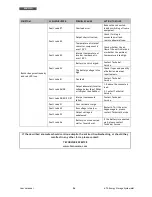
ATA Energy Storage System MM 


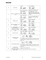
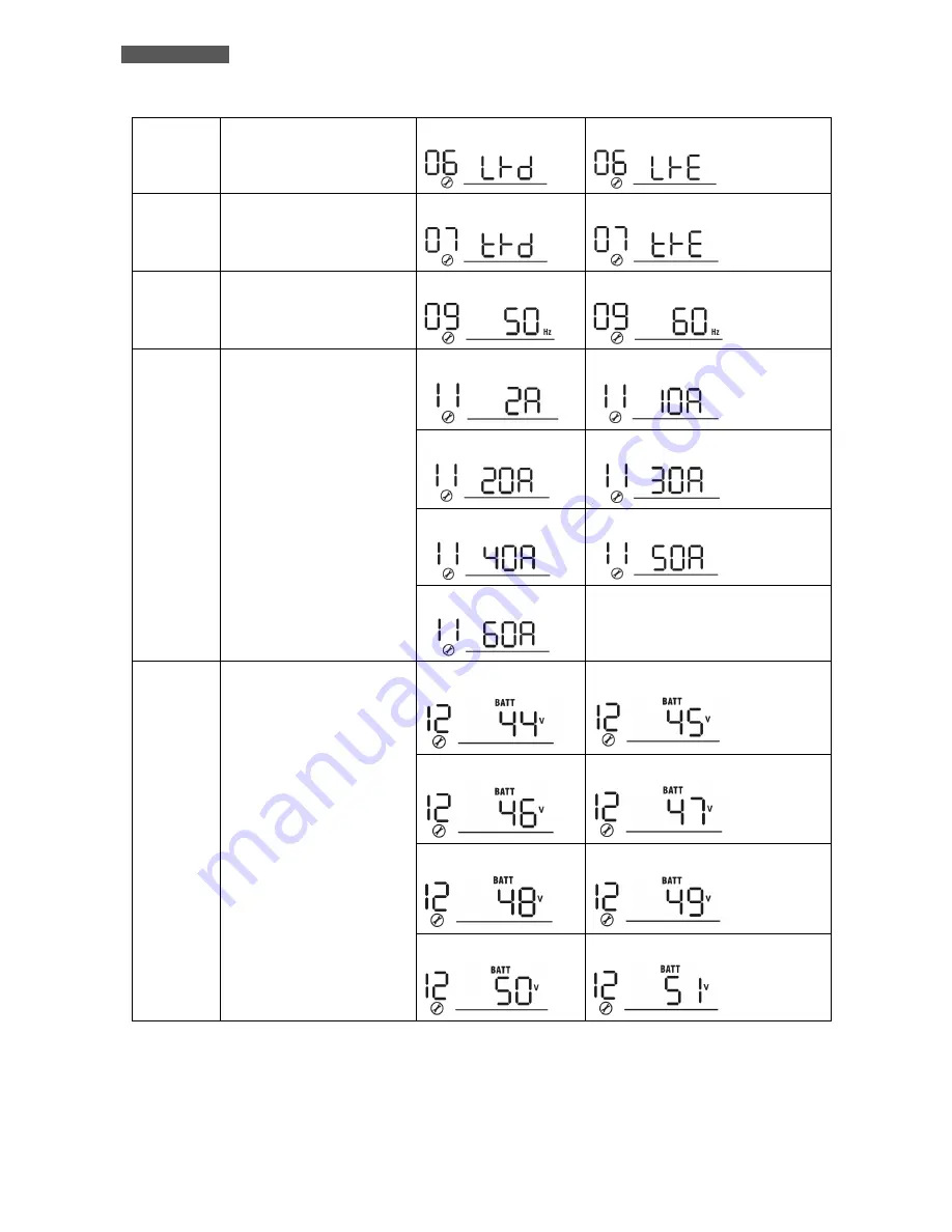
06 

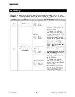
Auto restart when overload 

occurs 

Restart disable   


Restart enable 

(default)


07 

Auto restart when over 

temperature occurs 

Restart disable   


Restart enable 

(default)


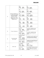
09 

Output frequency 

50Hz 

(default)


60Hz     


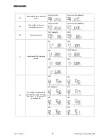
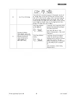
11 

Maximum utility charging 

current 

2A 


10A 


20A 


30A 

(default) 


40A 


50A


60A 


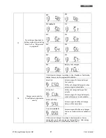
12 

Pre-setting voltage back to 

utility source when selecting 

“Solar first” or “SBU priority” 

in program 01. 

44V 


45V 


46V 

(default)


47V 


48V 


49V 


50V 


51V 


Содержание ATA 4.0 MM

Страница 1: ...Uninterruptible Power Supply ATA Energy Storage System ATA 4 0 MM ATA 5 0 MM User s manual Manuale utente...

Страница 2: ......

Страница 3: ...ow Battery and Automatic Restart 17 9 3 Load Testing 18 9 4 Operation in Warning Status 18 9 5 Operation in Fault Mode 19 10 Communication Interfaces 20 10 1 WatchPower 20 10 2 RS485 Interface 22 11 P...

Страница 4: ...42 12 9 Connections of Parallel Kit cables 42 12 10 Setting Parameter 43 12 11 Startup 44 12 12 Faults and Alarm 45 13 Technical Characteristics 46 14 Settings 48 15 Maintenance 54 15 1 ATA Cleaning 5...

Страница 5: ...imento 75 9 2 Fine Autonomia e Riaccensione Automatica 75 9 3 Controllo del Carico 76 9 4 Segnalazioni di Allarme 76 9 5 Segnalazioni di Guasto 77 10 Interfacce di Comunicazione 78 10 1 WatchPower 78...

Страница 6: ...vi del Kit 100 12 10 Impostazione Parametro 101 12 11 Messa in Servizio 102 12 12 Anomalie ed Allarmi del Sistema 103 13 Caratteristiche Tecniche 104 14 Settaggi 106 15 Manutenzione 112 15 1 Pulizia d...

Страница 7: ...rized by TECNOWARE TECNOWARE declines any responsibility if this warning is disregarded The electric installation has to be done by qualified personnel Follow all the Safety Standards CEI Standards in...

Страница 8: ...SYSTEM and connect the loads directly with the AC input main ATA ENERGY STORAGE SYSTEM is equipped with a communication interface RJ45 and USB that can be used to communicate with the software WatchPo...

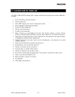
Страница 9: ...e of load frequency alarms overload fault and functioning modes 9 Available settings of all the UPS parameters by user through front panel pushbuttons and graphic LCD panel or through software install...

Страница 10: ...e careful in using a fixing system suitable to the mounting surface and to the weight of ATA TECNOWARE declines any responsibility if these warnings are disregarded 1 The ATA is designed to operate in...

Страница 11: ...U indicates the order of priority of the power supply used by ATA The first source is S SOLAR i e solar panels the second source is B BATTERY i e batteries the third source is U UTILITY i e the AC Uti...

Страница 12: ...not being sufficient will the equipment be powered automatically from the mains Should a blackout occur during this phase the ATA uses the 30 40 of energy remaining in the batteries UPS function to p...

Страница 13: ...sufficient ATA use the batteries energy To active this modality you need to set correctly the parameters 01 and 16 in the ATA settings See the chapter Settings 5 2 Only with the main UPS ATA system us...

Страница 14: ...ameters Front panel shown below consists of two parts 1 Graphic LCD panel provides complete information about the functioning status and existing alarms Load and Battery level Input Output and Battery...

Страница 15: ...Information Indicate output voltage output frequency load percent load in VA and load in Watt Battery Information Indicates battery level by 0 24 25 49 50 74 and 75 100 in battery mode and charging st...

Страница 16: ...e mode Flashing Output is powered by battery or PV in battery mode Blu Solid On Battery is fully charged Flashing Battery is charging Red Solid On Fault occurs in the inverter Flashing Warning conditi...

Страница 17: ...he PV panels 4 Battery Input to connect the ATA to the batteries 5 Input Circuit Breaker it goes off in Overload or short circuit condition push the external button of the Circuit Breaker to reactivat...

Страница 18: ...Circuit Breaker RCCB with leakage current protective function leakage current 30 mA It is also advisable to install a PV protection system between the PV panels line and the PV panels Input of ATA dim...

Страница 19: ...WG ATA 5 0 MM 8 mm2 or 8 AWG 8 mm2 or 8 AWG 2 x 8 mm2 or 2 x 8 AWG 2 cables together with a single cable lugs 8 mm2 or 8 AWG 8 mm2 or 8 AWG The wires for ATA 4 0 MM must be designed to withstand curre...

Страница 20: ...F ON OFF LOAD RCCB Residual Current Circuit Breaker 30mA existing RCCB Residual Current Circuit Breaker 300mA NEW ELECTRICITY METER existing PV PROTECTION SYSTEM PV PANELS ATA ENERGY STORAGE SYSTEM BO...

Страница 21: ...panels with a power of 250 Wp it will be able to achieve up to 5 strings of panels connected in parallel because The peak power of each string 3 x 250 750 Wp number of panels in a string multiplied b...

Страница 22: ...ormed exclusively by qualified technical personnel authorized by TECNOWARE TECNOWARE declines any responsibility if this warning is disregarded Disregard for these warnings may lead to a risk of elect...

Страница 23: ...completely OFF The ATA can be turned on even in the absence of production from PV panels and in the absence of AC mains 9 2 Low Battery and Automatic Restart The ATA reaches the Low Battery condition...

Страница 24: ...ion Do not connect a load greater than rated value to the ATA see POWER specifications in the chapter Technical Characteristics as this may damage the unit In this case the warranty is void 9 4 Operat...

Страница 25: ...V supply external Battery and Output immediately to avoid further risk or danger Below you can see the Fault Table with each Fault event and the relative FAULT code icon on graphic LCD for the user s...

Страница 26: ...nt from batteries battery capacity power output working frequency and other variables to set the ATA functioning parameters to record the data generated by the system to see the graphical representati...

Страница 27: ...backlight reboot in case of overload and or bypass etc to select the functioning mode SBU Utility etc to select the priority of power for the loads only by solar panels only by AC Utility Line hybrid...

Страница 28: ...ons such as sending e mail messages changing the default password setting the update times storing the values of the system and selecting historicizing and extrapolating the anomalies to an Excel file...

Страница 29: ...d specification ATA can be connected in parallel so the max handling power is 20KVA 16KW for ATA 5 0 MM 11 2 Parallel Kit The parallel kit consists of 11 3 Parallel Kit Installation 1 Remove the metal...

Страница 30: ...System MM 3 Remove the screws as shown below then remove the 2 pin flat cable remove the 14 pin flat cable and remove the electronic board placed under the communication board 4 Remove the metal cover...

Страница 31: ...ct the 2 pin and 14 pin flat cables to the Parallel board and Communication board as shown below 7 Install again the Communication board where it had been previously removed 8 Reassemble the metal cov...

Страница 32: ...eful to install the units at the same height 11 5 Batteries Connection ATTENTION the type of batteries set to each ATA must be identical otherwise the system reports error ATTENTION the length of the...

Страница 33: ...inverters in parallel The following table shows the recommended size for wires and battery terminals Recommended size for wires and battery terminals ATA MODEL AMPERES typical WIRE SIZE RING TERMINAL...

Страница 34: ...nnection of each ATA are to be placed under a protection system You can not install the security systems on the input NEUTRAL connection of each ATA The input NEUTRAL connections are placed in common...

Страница 35: ...of each ATA The Output NEUTRAL lines are placed in common on the NEUTRAL connecting bar ATTENTION be sure that the length of all the power cables is as similar as possible for each ATA so as to ensure...

Страница 36: ...Energy Storage System MM 11 9 Connections of Parallel Kit cables Refer to the figure below to connect the cables included in the kit parallel 2 ATA units in parallel mode 3 ATA units in parallel mode...

Страница 37: ...phase and 3P3 in program 28 for the inverters connected to L3 phase Be sure to connect share current cable to units which are on the same phase Do NOT connect share current cable between units on diff...

Страница 38: ...hen all of inverters are connected to PV modules For example two units are connected in parallel and set SOL in output source priority When selecting ALL in program 30 it s necessary to have all inver...

Страница 39: ...e ATA ATTENTION the Master and Slave units are randomly selected 4 Place the circuit breakers of PV panels in ON position 5 Turn ON all the protections of Input Line We recommended to connect all inve...

Страница 40: ...sharing cables are properly connected and restart the System 2 If the problem persists contact the Customer Service 80 Data communication loss 1 Be sure that the communication cables are properly conn...

Страница 41: ...specification ATA in parallel installing an ATA for each phase so the max handling power is 15KVA 12KW for ATA 5 0 MM 12 2 Parallel Kit The parallel kit consists of 12 3 Parallel Kit Installation 1 R...

Страница 42: ...System MM 3 Remove the screws as shown below then remove the 2 pin flat cable remove the 14 pin flat cable and remove the electronic board placed under the communication board 4 Remove the metal cover...

Страница 43: ...ct the 2 pin and 14 pin flat cables to the Parallel board and Communication board as shown below 7 Install again the Communication board where it had been previously removed 8 Reassemble the metal cov...

Страница 44: ...eful to install the units at the same height 12 5 Batteries Connection ATTENTION the type of batteries set to each ATA must be identical otherwise the system reports error ATTENTION the length of the...

Страница 45: ...inverters in parallel The following table shows the recommended size for wires and battery terminals Recommended size for wires and battery terminals ATA MODEL AMPERES typical WIRE SIZE RING TERMINAL...

Страница 46: ...and a protection device fuse on the NEUTRAL connection of the system Refer to the diagram below ATTENTION only the input LINE connection of each ATA are to be placed under a protection system You can...

Страница 47: ...LINE phase of each ATA unit Refer to the diagram below ATTENTION only the Output LINE connection of each ATA are to be placed under a protection system You can not install the security systems on the...

Страница 48: ...anels You can not use only one system of PV panels in common for all ATA units 12 9 Connections of Parallel Kit cables Refer to the figure below to connect the cables included in the kit parallel Belo...

Страница 49: ...phase and 3P3 in program 28 for the inverters connected to L3 phase Be sure to connect share current cable to units which are on the same phase Do NOT connect share current cable between units on diff...

Страница 50: ...e protection systems on the Input LINE connections are open and Input NEUTRAL connections are connected in common 2 Place the circuit breaker of batteries in ON position 3 Place the On Off switch of t...

Страница 51: ...haring cables are properly connected and restart the System 4 If the problem persists contact the Customer Service 80 Data communication loss 1 Be sure that the communication cables are properly conne...

Страница 52: ...Hz automatic selection INPUT PHOTOVOLTAIC PANELS Maximum PV array power 3750 Wp MPPT range operating voltage 60 115 Vdc Maximum PV array oper circuit power 145 Vdc Maximum PV array input current 60 A...

Страница 53: ...8 UNIX LINUX ecc External RS485 interface Yes optional PARALLEL CONFIGURATION Parallel interface Yes optional Parallel unit Up to 4 units ENVIROMENTAL SPECIFICATION Storage temperature From 15 to 60...

Страница 54: ...gy will supply power the loads at the same time Utility provides power to the loads only when any one condition happens Solar energy is not available Battery voltage drops to either low level warning...

Страница 55: ...ltage range will be within 90 280VAC UPS default If selected acceptable AC input voltage range will be within 170 280VAC 04 Power saving mode enable disable Saving mode disable default If disabled no...

Страница 56: ...Auto restart when over temperature occurs Restart disable Restart enable default 09 Output frequency 50Hz default 60Hz 11 Maximum utility charging current 2A 10A 20A 30A default 40A 50A 60A 12 Pre set...

Страница 57: ...Solar energy will charge battery as first priority Utility will charge battery only when solar energy is not available Utility first Utility will charge battery as first priority Solar energy will ch...

Страница 58: ...errupted Alarm on Alarm off default 23 Overload bypass When enabled the unit will transfer to line mode if overload occurs in battery mode Bypass disable Bypass enable default 25 Record Fault code Rec...

Страница 59: ...tage is 4V higher than cut off voltage 31 Solar power balance When enabled solar input power will be automatically adjusted according to connected load power Only available for 4KVA 5KVA model Solar P...

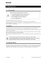
Страница 60: ...ree months go through the procedure described in the chapter First Start Up before using it again Battery life strongly depends on the ambient temperature There are also other factors like the number...

Страница 61: ...he ATA contains internal parts which are at a high Voltage and are potentially dangerous capable of causing injury or death by electric shock There are no internal parts in the ATA which are user serv...

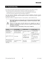
Страница 62: ...tage is too high Check if spec and quantity of batteries are meet requirements Fault code 01 Fan fault Contact Technical Service Fault code 06 58 Output abnormal Inverter voltage below than 190Vac or...

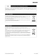
Страница 63: ...mbol marked by a cross help to avoid negative consequences to the environment and to human health Lead Batteries ATA ENERGY STORAGE SYSTEM models contain lead acid sealed maintenance free batteries Th...

Страница 64: ...ENGLISH User s manual 58 ATA Energy Storage System MM...

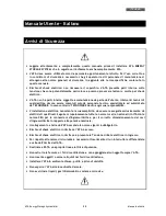
Страница 65: ...TECNOWARE In caso contrario TECNOWARE declina ogni sua responsabilit L installazione elettrica nonostante la sua semplicit deve essere eseguita esclusivamente da elettricisti qualificati Seguire scrup...

Страница 66: ...ea elettrica d Ingresso alle uscite ATA ENERGY STORAGE SYSTEM dotato d interfacce di comunicazione RJ45 RS232 e USB che possono essere utilizzate per la comunicazione con il programma WatchPower Legge...

Страница 67: ...armi guasti e dei vari modi di funzionamento 9 Configurazione e settaggio da parte dell utente dei parametri di funzionamento tramite pannello frontale e display grafico o tramite software installato...

Страница 68: ...enzione nell utilizzare un sistema di fissaggio adeguato alla superficie di installazione e al peso dell ATA In caso contrario TECNOWARE declina ogni sua responsabilit 1 L ATA progettato per operare i...

Страница 69: ...gla SBU indica l ordine di priorit della fonte di alimentazione utilizzata da ATA La prima fonte S SOLAR cio i pannelli fotovoltaici la seconda fonte B BATTERY cio le batterie la terza fonte U UTILITY...

Страница 70: ...arecchiature vengono alimentate automaticamente dalla rete elettrica In questa fase le batterie non vengono ricaricate dalla rete elettrica Se in questa fase si verifica un black out ATA utilizza il 3...

Страница 71: ...nergia delle batterie Per attivare questa modalit necessario entrare nei settaggi di ATA e impostare correttamente i parametri 01 e 16 Vedere capitolo Settaggi 5 2 Modalit Utility solo con la Rete Ele...

Страница 72: ...1 Un pannello LCD grafico che fornisce le informazioni complete sullo stato di funzionamento per i vari modi di funzionamento sugli allarmi esistenti sul carico in Uscita sulle batterie e sulle misur...

Страница 73: ...e Uscita Indica la tensione di uscita frequenza di uscita percentuale di carico carico espresso in VA e in Watt Batterie Indica il livello batterie da 0 24 25 49 50 74 e 75 100 in modalit batteria e i...

Страница 74: ...alimentata dai pannelli fotovoltaici o dalle batterie Verde Fisso Batterie completamente cariche Lampeggiante Batterie in carica Rosso Fisso Guasto o problematica su ATA Lampeggiante Allarme su ATA Pu...

Страница 75: ...4 Ingresso batterie per connettere ATA alle batterie 5 Interruttore termico d ingresso rete l interruttore scatta in caso di sovraccarico o cortocircuito per riarmare l interruttore occorre premere ma...

Страница 76: ...no essere installati secondo le norme vigenti Inoltre opportuno installare un quadro di campo tra la linea dei pannelli fotovoltaici e l ingresso dei pannelli fotovoltaici sull ATA dimensionato in bas...

Страница 77: ...in uscita Per sicurezza e affidabilit occorre utilizzare cavi con sezione non inferiore a quelli indicati nella tabella sopra riportata I cavi di ATA 5 0 MM devono essere dimensionati per sopportare...

Страница 78: ...O DIFFERENZIALE 30mA GIA ESISTENTE INTERRUTTORE MAGNETOTERMICO DIFFERENZIALE 300mA NUOVO CONTATORE GIA ESISTENTE QUADRO DI CAMPO PANNELLI FOTOVOLTAICI ATA ENERGY STORAGE SYSTEM BOX BATTERIE ATA RETE D...

Страница 79: ...izzando pannelli fotovoltaici con potenza pari a 250Wp sar possibile realizzare fino ad un massimo di 5 paralleli stringhe in quanto Potenza massima di ogni stringa 3 x 250 750Wp numero di pannelli mo...

Страница 80: ...ializzato ed autorizzato da TECNOWARE In caso contrario TECNOWARE declina ogni sua responsabilit Non rispettare queste precauzioni espone l operatore al pericolo di shock elettrico 8 Prima Accensione...

Страница 81: ...zione da pannelli fotovoltaici e in assenza di rete elettrica 9 2 Fine Autonomia e Riaccensione Automatica L ATA raggiunge la condizione di Fine Autonomia o Low Battery quando le batterie raggiungono...

Страница 82: ...del capitolo Caratteristiche Tecniche in quanto pu esserne danneggiato In tal caso vengono a decadere le condizioni di garanzia 9 4 Segnalazioni di Allarme La condizione di Allarme segnalata dall emis...

Страница 83: ...e ulteriori rischi o danni disconnettere l ATA dalla linea d Ingresso da box batterie esterni dai pannelli PV e dalle linee d Uscita Di seguito riportata la Tabella Fault con elencati tutti i tipi di...

Страница 84: ...uenza di lavoro ed altro impostare i parametri di funzionamento dell ATA registrazione dei dati generati dal sistema visualizzare su rappresentazione grafica l andamento nel tempo dei dati registrati...

Страница 85: ...schermo riavvio in caso di sovraccarico e o bypass ed ecc modalit di funzionamento SBU impostato di default Utility ed ecc priorit di alimentazione del carico solo da pannelli fotovoltaici solo da re...

Страница 86: ...zione dei tempi di aggiornamento e memorizzazione dei valori di funzionamento del sistema e la selezione la storicizzazione e l estrapolazione su foglio excel delle anomalie di funzionamento Accedendo...

Страница 87: ...supportabile di 20KVA 16KW per ATA 5 0 MM 11 2 Contenuto Confezione del Kit Parallelo Sotto riportato il contenuto della confezione 11 3 Installazione Kit Parallelo 1 Rimuovere il pannello metallico c...

Страница 88: ...Rimuovere le viti come riportato nell immagine sottostante e in seguito rimuovere il flat a 2 e 14 pin e la scheda posta sotto quella comunicazione 4 Rimuovere il coperchio metallico come riportato n...

Страница 89: ...tere i flat a 2 e 14 pin sulla scheda parallelo e comunicazioni Vedi immagini sottostanti 7 Installare nuovamente la scheda comunicazioni dove era stata rimossa in precedenza 8 Rimontare il coperchio...

Страница 90: ...llare le unit alla stessa altezza 11 5 Connessione Batterie ATTENZIONE La tipologia di batterie impostata su ogni ATA deve essere identica altrimenti il sistema va in errore ATTENZIONE la lunghezza de...

Страница 91: ...erter posti in parallelo Per il dimensionamento dei cablaggi fare riferimento alla tabelle sottostante Dimensionamento cablaggi e terminali batterie MODELLO ATA AMPERAGGIO TIPICO DIMENSIONE CABLAGGI T...

Страница 92: ...ssibile installare dei sistemi di protezione su la linea di neutro di ogni ATA Le linee di neutro sono poste in comune sulla rispettiva barra di connessione La protezione della linea di neutro deve es...

Страница 93: ...tiva barra di connessione ATTENZIONE Verificare che la lunghezza di tutti i cavi di alimentazione sia il pi simile possibile per ogni unit ATA in modo da garantire un equa distribuzione della corrente...

Страница 94: ...ATA Energy Storage System MM 11 9 Connessione Cavi del Kit Fare riferimento all immagine sottostante per la connessione dei cavi compresi nel kit parallelo 2 unit ATA in parallelo 3 unit ATA in parall...

Страница 95: ...zo PV applicabile al solo settaggio Solar first nel parametro 1 Priorit alimentazione uscita 1 Inverter Default Quando selezionata la voce ONE fin quando un inverter connesso ai pannelli PV e la tensi...

Страница 96: ...re secondo il principio di funzionamento dell impostazione solar first Per esempio due inverter sono collegati in parallelo ed impostata la funzione SOL nel parametro priorit alimentazione uscita In q...

Страница 97: ...NE Le unit Master e Slave sono selezionate casualmente 4 Portare su ON gli interruttori dei pannelli fotovoltaici 5 Portare su ON tutti gli interruttori a protezione della linea d ingresso E consiglia...

Страница 98: ...cavi di sharing siano collegati correttamente e riavviare il sistema 2 Se il problema persiste contattare il Servizio Assistenza 80 Perdita dati comunicazione 2 Controllare che i cavi di comunicazioni...

Страница 99: ...sima potenza supportabile di 15KVA 12KW per ATA 5 0 MM 12 2 Contenuto Confezione Kit Parallelo Sotto riportato il contenuto della confezione 12 3 Installazione Kit Parallelo 1 Rimuovere il pannello me...

Страница 100: ...Rimuovere le viti come riportato nell immagine sottostante e in seguito rimuovere il flat a 2 e 14 pin e la scheda posta sotto quella comunicazione 4 Rimuovere il coperchio metallico come riportato n...

Страница 101: ...tere i flat a 2 e 14 pin sulla scheda parallelo e comunicazioni Vedi immagini sottostanti 7 Installare nuovamente la scheda comunicazioni dove era stata rimossa in precedenza 8 Rimontare il coperchio...

Страница 102: ...llare le unit alla stessa altezza 12 5 Connessione Batterie ATTENZIONE La tipologia di batterie impostata su ogni ATA deve essere identica altrimenti il sistema va in errore ATTENZIONE la lunghezza de...

Страница 103: ...inverter posti in parallelo Per il dimensionamento dei cablaggi fare riferimento alla tabelle sottostante Dimensionamento cablaggi e terminali batterie MODELLO ATA AMPERAGGIO TIPICO DIMENSIONE CABLAGG...

Страница 104: ...sono da porre un sotto sistema di protezione Non possibile installare dei sistemi di protezione su la linea di neutro di ogni ATA Le linee di neutro sono poste in comune sulla rispettiva barra di con...

Страница 105: ...e di fase di ogni ATA sono da porre un sotto sistema di protezione Non possibile installare dei sistemi di protezione su la linea di neutro di ogni ATA Le linee di neutro sono poste in comune sulla ri...

Страница 106: ...on possibile utilizzare un sistema di pannelli fotovoltaici in comune per tutte le unit ATA 12 9 Connessione Cavi del Kit Fare riferimento all immagine sottostante per la connessione dei cavi compresi...

Страница 107: ...tiva la modalit di risparmio energia viene disabilitata Parallelo Fase L1 Fase L2 Fase L3 30 Condizione Utilizzo PV applicabile al solo settaggio Solar first nel parametro 1 Priorit alimentazione usci...

Страница 108: ...alimentato dalla rete elettrica 12 11 Messa in Servizio 1 Controllare di aver rispettato le seguenti specifiche prima della messa in servizio del sistema Controllare le connessioni all interno del sis...

Страница 109: ...esso firmware 2 Se il problema persiste contattare il Servizio Assistenza 72 La corrente di uscita per ogni inverter differente 1 Controllare che i cavi di sharing siano collegati correttamente e riav...

Страница 110: ...e 50 60 Hz selezione automatica INGRESSO PANNELLI FOTOVOLTAICI Potenza massima PV 3750 Wp Campo di lavoro tensione MPPT 60 115 Vdc Massima tensione a circuito aperto PV 145 Vdc Massima corrente da PV...

Страница 111: ...ia esterna RS485 Si opzionale CONFIGURAZIONE PARALLELO Interfaccia parallelo Si opzionale Unit parallelabili Fino a 4 unit CONDIZIONI AMBIENTALI OPERATIVE Temperatura di stoccaggio Da 15 a 60 C Temper...

Страница 112: ...tribuiscono ad alimentare il carico nello stesso momento La rete alimenta il carico solo al verificarsi di uno dei seguenti casi l energia dai pannelli solari non disponibile la tensione delle batteri...

Страница 113: ...d ingresso Carichi domestici Se selezionato accetta una tensione d ingresso compresa tra 90 e 280Vac UPS default Se selezionato accetta una tensione d ingresso compresa tra 170 e 280Vac 04 Modalit ri...

Страница 114: ...equenza d uscita 50Hz default 60Hz 11 Massima corrente di ricarica da rete elettrica 2A 10A 20A 30A default 40A 50A 60A 12 Valore minimo tensione batterie per il quale il carico viene alimentato dalla...

Страница 115: ...sotto riportato Solar first Come priorit le batterie vengono ricaricate dai pannelli solari La rete ricarica le batterie solo quando l energia dai pannelli solari non presente Utility first Come prio...

Страница 116: ...vo ATA trasferisce il carico sulla rete elettrica quando si verifica un sovraccarico durante la modalit batteria Bypass attivo default Bypass disattivo 25 Memorizzazione codici di allarme Memorizzazio...

Страница 117: ...sta questi si riavvia automaticamente quando viene raggiunto almeno un valore pari a 4V sopra il valore impostato 31 Funzione Solar power balance Quando attivata l energia corrente proveniente dai pan...

Страница 118: ...almente svolgere la procedura di Prima Accensione descritta nell omonimo capitolo di questo manuale La durata delle batterie dipende fortemente dalla temperatura dell ambiente di lavoro oltre ad altri...

Страница 119: ...azioni consigliate non avessero esito positivo contattare il Servizio Assistenza Rischio di shock elettrico Non smontare l ATA contiene parti sotto tensione che sono potenzialmente pericolose e posso...

Страница 120: ...e specifiche delle batterie rientrino in quelle indicate Codice errore 01 Errore ventola Contattare il Servizio Assistenza Codice errore 06 58 Uscita anomala tensione al di sotto di 190Vac o al di sop...

Страница 121: ...e aiuta ad evitare possibili conseguenze negative per l ambiente e la salute umana Batterie al Piombo Il prodotto ATA ENERGY STORAGE SYSTEM contiene batterie al piombo acido ermetiche senza manutenzio...

Страница 122: ...ved All trademarks are property of their respective owners TECNOWARE s r l Via Montetrini 2E Loc Molino del Piano 50065 Pontassieve FI Italy www tecnoware com This manual has been printed and edited b...

Страница 123: ......

Страница 124: ...TECNOWARE s r l www tecnoware com...

Отзывы: