


TD20 Series VFD
Function Parameters
-71-
Function
code
Name
Detailed instruction of parameters
Default
value
Modify
Setting range of P09.12: 0.0
–3600.0s
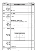
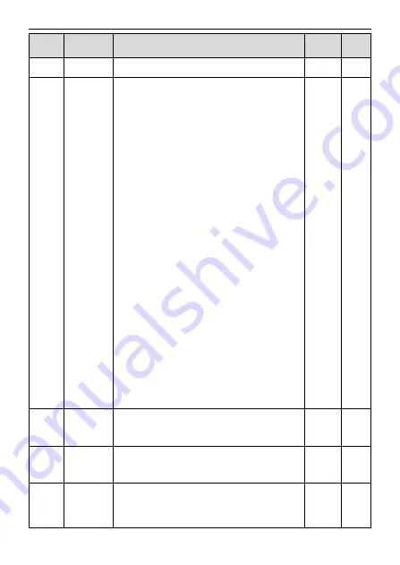
P09.13
PID
adjustment
selection
0x00
–0x11
LED ones:
0: Keep on integral adjustment when the frequency
achieves the upper and low limit; the integration shows
the change between the reference and the feedback
unless it reaches the internal integral limit. When the
trend between the reference and the feedback changes,
it needs more time to offset the impact of continuous
working and the integration will change with the trend.
1: Stop integral adjustment when the frequency reaches
the upper and low limit. If the integration keeps stable,
and the trend between the reference and the feedback
changes, the integration will change with the trend
quickly.
LED tens:
0: The same with the setting direction; if the output of
PID adjustment is different from the current running
direction, the internal will output 0 forcedly.
1: Opposite to the setting direction
LED hundreds:
0: Limit to the maximum frequency
1: Limit to A frequency
LED thousands:
0: A+B frequency, buffer ACC/DEC is invalid for the
main reference A frequency source
1: A+B frequency, buffer ACC/DEC is valid for the main
reference A frequency source and the ACC/DEC is
determined by time 4 of P08.04
0x0001
○
P09.14
Proportional
gain at low
frequency (Kp)
0.00
–100.00
1.00
○
P09.15
PID command
of ACC/DEC
time
0.0
–1000.0s
0.0s
○
P09.16
PID output
filter time
0.000
–10.000s
0.000s
○
Содержание TD20 Series
Страница 1: ......
Страница 129: ...TD20 Series VFD Appendix C Peripheral Options and Parts 127 PB External brake resistor TD20...
Страница 131: ......


