


TD20 Series VFD
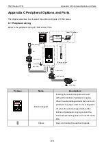
Appendix C Peripheral Options and Parts
-121-
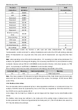
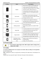
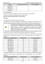
Pictures
Name
Descriptions
Breaker
Prevent from electric shock and protect the
power supply and the cables system from
overcurrent when short circuits occur. (Please
select the breaker with the function of
reducing high order harmonic and the rated
sensitive current to 1 VFD should be above
30mA).
Input reactor
This device is used to improve the power
factor of the input side of the VFD and control
the
higher harmonic current.
Input filter
Control the electromagnetic interference
generated from the VFD, please install close
to the input terminal side of the VFD.
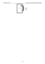
Braking resistors
Shorten the DEC time.
Only braking resistors are needed for TD20
VFDs.
Output filter
Control the interference from the output side
of the VFD and please install close to the
output terminals of the VFD.
Output reactor
Prolong the effective transmitting distance of
the VFD to control the sudden high voltage
when switching on/off the IGBT of the VFD.
Membrane of heat
releasing holes at the
side
Apply to severe environment and improve
protective effect.
Derate 10% of the machine.
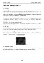
C.2 Power supply
•
Check that the voltage degree of the VFD complies with the voltage of the
supply power voltage.
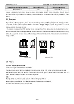
C.3 Cables
C.3.1 Power cablesDimension the input power and motor cables according to local regulations.
Use 75°C CU wire only.
Note:
A separate PE conductor is required if the conductivity of the cable shield is not sufficient for the
purpose.
Required wire torque, type and range for field input and output terminals listed below:
Содержание TD20 Series
Страница 1: ......
Страница 129: ...TD20 Series VFD Appendix C Peripheral Options and Parts 127 PB External brake resistor TD20...
Страница 131: ......


