TD20 Series VFD
Installation Guide
-12-
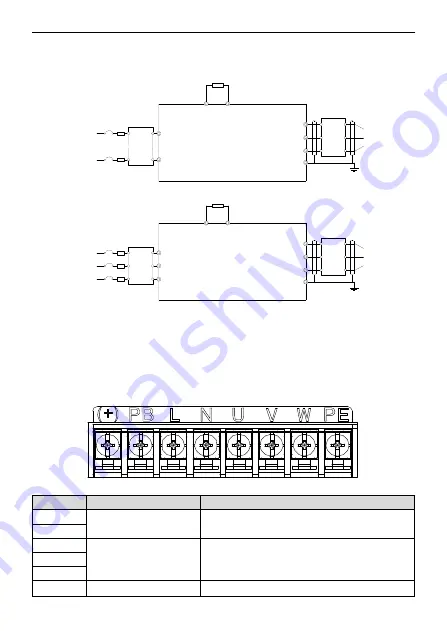
3.2 Standard wiring
3.2.1 Connection diagram of main circuit
R
S
T
W
V
U
PE
M
(+)
PB
Three-phase
380V~480V
50/60Hz
Brake resistor
Input
reactor
Input
filter
Fuse
Output
reactor
Output
filter
L
N
W
V
U
PE
M
(+)
PB
Single-phase
200V~240V
50/60Hz
Brake resistor
Input
reactor
Input
filter
Fuse
Output
reactor
Output
filter
Figure 3-3 Connection diagram of main circuit
Note:
•
The fuse, braking resistor, input reactor, input filter, output reactor, output filter are optional parts.
Please refer to
Peripheral Optional Parts
for detailed information.
•
Remove the yellow warning labels of PB, (+) and (-) on the terminals before connecting the braking
resistor; otherwise, poor connection may occur.
3.2.2 Terminals figure of main circuit
Figure 3-4 1PH terminals of main circuit
Terminal
Terminal name
Function
L
Power input of the main circuit
1-phase AC input terminals which are generally
connected with the power supply.
N
U
The VFD output
3-phase AC output terminals which are generally
connected with the motor.
V
W
PB, (+)
Braking resistor terminal
PB and (+) are connected to the external resistor.
Содержание TD20 Series
Страница 1: ......
Страница 129: ...TD20 Series VFD Appendix C Peripheral Options and Parts 127 PB External brake resistor TD20...
Страница 131: ......


