background image

TD20 Series VFD 

Function Parameters 

-32- 

Function 

code 

Name 

Detailed instruction of parameters 

Default 

value 

Modify 

decreases to 0Hz, the VFD stops.   

1: Coast to stop: after the stop command becomes valid, 

the VFD ceases the output immediately. And the load 

coasts to stop at the mechanical inertia. 

P01.09 

Starting 

frequency of 

DC braking 

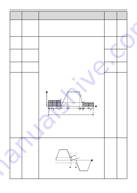
Starting frequency of DC braking: start the DC braking 

when running frequency reaches starting frequency 

determined by P1.09. 

Waiting time before DC braking: VFDs blocks the output 

before starting the DC braking. After this waiting time, 

the DC braking will be started so as to prevent 

over-current fault caused by DC braking at high speed. 

DC braking current: the value of P01.11 is the 

percentage of rated current of VFD. The bigger the DC 

braking current is, the greater the braking torque is.   

DC braking time: the retention time of DC braking. If the 

time is 0, the DC braking is invalid. The VFD will stop at 

the set deceleration time.   

P01.04

ACC

P13.14

P01.23

Constant

speed

In running

DEC

P0110

P13.14

P01.12

P01.09

t


Setting range of P01.09: 0.00Hz

–P00.03 

(the Max. frequency) 

Setting range of P01.10: 0.00

–50.00s 

Setting range of P01.11: 0.0

–100.0% 

Setting range of P01.12: 0.00

–50.00s 

0.00Hz 

○ 

P01.10 

Waiting time 

before DC 

braking 

0.00s 

○ 

P01.11 

DC braking 

current 

0.0% 

○ 

P01.12 

DC braking 

time 

0.00s 

○ 

P01.13 

Dead time of 

FWD/REV 

rotation 

During the procedure of switching FWD/REV rotation, 

set the threshold by P01.14, which is as the table below:   

Output frequency


FWD

REV

T

Starting

frequency


Shift after the

Zero frequency


Shift after the

Starting frequency


Setting range: 0.0

–3600.0s 

0.0s 

○ 

Содержание TD20 Series

Страница 1: ......

Страница 2: ...meters 24 6 Fault Tracking 85 6 1 Maintenance intervals 85 6 2 Fault solution 88 7 Communication Protocol 95 7 1 Brief instruction to Modbus protocol 95 7 2 Application of the VFD 95 7 3 RTU command c...

Страница 3: ...ectricians People working on the device should take part in professional electrical and safety training receive the certification and be familiar with all steps and requirements of installing commissi...

Страница 4: ...t the braking optional parts braking resistors braking units or feedback units according to the wiring diagram Do not operate on the VFD if there is any damage or components loss to the VFD Do not tou...

Страница 5: ...For VFDs that have been stored for a long time check and fix the capacitance and try to run it again before utilization see Maintenance and Hardware Fault Diagnose Cover the front board before runnin...

Страница 6: ...rk and check whether the power degree of the VFD needs to be modified 2 Check that the actual current of the motor is less than the rated current of the VFD 3 Check that the control accuracy of the lo...

Страница 7: ...al 7 Check that the installation conforms to the instructions in user s manual The VFD must be installed in an upright position 8 Check that the external connection terminals are tightly fastened and...

Страница 8: ...D setting MODBUS communication setting Shift between the set combination and set channel Auto adjustment of the voltage Keep a stable voltage automatically when the grid voltage transients Fault prote...

Страница 9: ...e suitable for overvoltage category III and shall provide protection for a rated impulse withstand voltage peak of 4kV or equivalent 3PH Used in Canada only Transient surge suppression shall be instal...

Страница 10: ...80V 480V 2 5 Rated specifications Model Rated output power kW Rated output horsepower HP Rated input current A Rated output current A TD20 0R4G S1 0 4 0 5 8 1 2 5 TD20 0R7G S1 0 75 1 15 1 4 2 TD20 1R1...

Страница 11: ...s of the main circuit 6 Nameplate See Product Overview for detailed information 7 Potentiometer knob Refer to the Keypad Operation Procedure 8 Control terminals See Electric Installation for detailed...

Страница 12: ...le functions of the VFD Check the installation environment as follows Environment Conditions Installation site Indoor Environment temperature 10 C 50 C and the temperature changing rate is less than 0...

Страница 13: ...ed in a clean and ventilated environment according to enclosure classification Cooling air must be clean free from corrosive materials and electrically conductive dust 3 1 2 Installation direction The...

Страница 14: ...ter output reactor output filter are optional parts Please refer to Peripheral Optional Parts for detailed information Remove the yellow warning labels of PB and on the terminals before connecting the...

Страница 15: ...symmetrically grounding conductor in the motor cable in addition to the conductive shield connect the grounding conductor to the grounding terminal at the VFD and motor ends Route the motor cable inp...

Страница 16: ...RO2B RO2C Figure 3 6 Wiring of control circuit 3 2 5 Terminals of control circuit ON GND Figure 3 7 Terminals of control circuit Type Terminal name Function description Technical specifications Commu...

Страница 17: ...current input can be set by dip switch 4 Resolution the minimum AI2 AI3 is 10mV 20mV when 10V corresponds to 60Hz AI3 GND Analog reference ground Analog reference ground AO1 Analog output 1 Output ran...

Страница 18: ...ower supply S1 S2 COM PW 24V COM 24V S1 S2 COM PW 24V COM 24V 24V Figure 3 9 NPN modes If the signal is from PNP transistor please set the U shaped contact tag as below according to the used power sup...

Страница 19: ...ting each cable and motor These devices may require a separate fuse to cut off the short circuit current 3 3 3 Implementing a bypass connection It is necessary to set power frequency and variable freq...

Страница 20: ...s that the VFD is in the stopping state LED blinking means the VFD is in the parameter autotune state LED on means the VFD is in the running state FWD REV FED REV LED LED off means the VFD is in the f...

Страница 21: ...quency and output frequency Displayed word Correspo nding word Displaye d word Correspo nding word Displaye d word Correspo nding word 0 1 2 3 4 5 6 7 8 9 A B C d E F H I L N n o P r S t U v 4 Buttons...

Страница 22: ...ypad AI1 otherwise the external keypad AI1 will be valid and P17 19 will be the voltage of the external keypad AI1 Note If the external keypad AI1 is frequency reference source adjust the local potent...

Страница 23: ...ayed state of fault If the VFD detects the fault signal it will enter into the fault pre alarm displaying state The keypad will display the fault code by flicking The TRIP LED on the keypad is on and...

Страница 24: ...ace is blinking The units place is blinking Note When setting the value you can press and to modify the value SHIFT Figure 4 3 Sketch map of modifying parameters 4 3 2 How to set the password of the V...

Страница 25: ...enter into P17 directly to watch the state PRC ESC PRC ESC DATA ENT PRC ESC DATA ENT The units place is blinking All digits are blinking The units place is blinking The units place is blinking Note Wh...

Страница 26: ...e modifying character of function codes the parameters can be modified or not and the modifying conditions below is the instruction means the set value of the parameter can be modified on stop and run...

Страница 27: ...need to pay attention to this parameter because it is the foundation of the frequency setting and the speed of acceleration and deceleration Setting range P00 04 400 00Hz 60 00Hz P00 04 Upper limit of...

Страница 28: ...n function code P00 03 4 High speed pulse HDI setting The frequency is set by high speed pulse terminals TD20 series VFDs provide 1 high speed pulse input as the standard configuration The pulse frequ...

Страница 29: ...nication See P14 for detailed information 9 11 Reserved Note A frequency and B frequency can not set as the same frequency given method P00 08 B frequency command reference selection 0 Maximum output...

Страница 30: ...D runs in the forward direction FWD REV indicator is off 1 Runs at the opposite direction the VFD runs in the reverse direction FWD REV indicator is on Modify the function code to shift the rotation d...

Страница 31: ...ncy when the VFD is in factory In general users do not need to change the parameter When the frequency used exceeds the default carrier frequency the VFD needs to derate 20 for each additional 1k carr...

Страница 32: ...ion may occur to the low inertia load during starting 2 Reserved Note It is recommended to start the synchronous motor directly 0 P01 01 Starting frequency of direct start up Starting frequency of dir...

Страница 33: ...ted current of the VFD The setting range of P01 03 0 0 100 0 The setting range of P01 04 0 00 50 00s 0 0 P01 04 The braking time before starting 0 00s P01 05 ACC DEC selection The changing mode of the...

Страница 34: ...1 11 is the percentage of rated current of VFD The bigger the DC braking current is the greater the braking torque is DC braking time the retention time of DC braking If the time is 0 the DC braking i...

Страница 35: ...quency P01 24 P01 17 B C Running A Running B Running C Setting range 0 00 100 00s only valid when P01 16 1 0 50s P01 18 Terminal running protection selection when powering on When the running command...

Страница 36: ...to stand by When the set frequency is above the lower limit one again and it lasts for the time set by P01 20 the VFD will run automatically Running Dormancy t1 t2 Running Time Set frequency t1 t3 so...

Страница 37: ...0Hz output Select the 0Hz output of the VFD 0 Output without voltage 1 Output with voltage 2 Output at the DC braking current 0 P02 Group Motor 1 P02 01 Rated power of asynchronous motor 0 1 3000 0kW...

Страница 38: ...nchronous motor 0 1 6553 5mH Depend on model P02 09 Mutual inductance of asynchronous motor 0 1 6553 5mH Depend on model P02 10 Non load current of asynchronous motor 0 1 6553 5A Depend on model P02 1...

Страница 39: ...of the specific motors won t be impacted by the rotation speed it is not necessary to adjust the protection value during low speed running 2 P02 27 Motor overload protection coefficient Times of motor...

Страница 40: ...0 10 000s The setting range of P03 02 0 00Hz P00 05 The setting range of P03 05 P03 02 P00 03 20 0 P03 01 Speed loop integral time1 0 200s P03 02 Low switching frequency 5 00Hz P03 03 Speed loop propo...

Страница 41: ...or rated current 50 0 P03 13 Torque given filter time 0 000 10 000s 0 100s P03 14 Setting source of forward rotation upper limit frequency in torque control 0 keypad setting upper limit frequency P03...

Страница 42: ...1 8 100 corresponds to three times of the motor current 0 P03 19 Upper limit setting of braking torque 0 P03 20 Electromotion torque upper limit keypad setting The function code is used to set the li...

Страница 43: ...to the constant torque load 1 Multi dots V F curve 2 1 3th power low torque V F curve 3 1 7th power low torque V F curve 4 2 0th power low torque V F curve Curves 2 4 apply to the torque loads such as...

Страница 44: ...ld below this frequency point the torque boost is valid but over this frequency point the torque boost is invalid Output voltage Output frequency fCut off fb Vb Vboost The setting range of P04 01 0 0...

Страница 45: ...ting range 0 0 200 0 100 0 P04 10 Low frequency vibration control factor In the SVPWM control mode current fluctuation may occur to the motor on some frequency especially the motor with big power The...

Страница 46: ...um voltage Voltage decreasing time is the time when the VFD decelerates from the output maximum voltage to the output minimum voltage Setting range 0 0 3600 0s 5 0s P04 30 Voltage decreasing time 5 0s...

Страница 47: ...tween A setting and B setting 14 Shift between combination setting and A setting 15 Shift between combination setting and B setting 16 Multi step speed terminal 1 17 Multi step speed terminal 2 18 Mul...

Страница 48: ...put terminal is cathode BIT8 BIT7 BIT6 BIT5 BIT4 HDI S8 S7 S6 S5 BIT3 BIT2 BIT1 BIT0 S4 S3 S2 S1 The setting range 0x000 0x1FF 0x000 P05 11 Switch filter time Set the sample filter time of S1 S4 and H...

Страница 49: ...ng ones The direction depends on the state of the defined REV FWD REV COM K1 K2 Running command FWD REV OFF OFF OFF OFF ON ON ON ON Stopping Stopping Forward running Reverse running 2 3 wire control 1...

Страница 50: ...stopping command from other sources even the control terminal FWD REV keeps valid the VFD won t work when the stopping command is canceled Only when FWD REV is relaunched the VFD can start again For e...

Страница 51: ...rminal AI2 and AI3 is set by control terminal AI3 The function code defines the relationship between the analog input voltage and its corresponding set value If the analog input voltage beyond the set...

Страница 52: ...00V P05 39 Setting range of P05 38 100 0 100 0 Setting range of P05 39 P05 37 10 00V Setting range of P05 40 100 0 100 0 Setting range of P05 41 0 000s 10 000s Setting range of P05 42 10 00V P05 44 Se...

Страница 53: ...ion 3 Reverse rotation operation 4 Jogging operation 5 The VFD fault 6 Frequency degree test FDT1 7 Frequency degree test FDT2 8 Frequency arrival 9 Zero speed running 10 Upper limit frequency arrival...

Страница 54: ...ing delay time of the electrical level change during the programmable terminal switching on and off RO electrical level RO valid Invalid Switch on delay Invalid Valid Switch off delay Setting range 0...

Страница 55: ...mum or minimum output it will count according to the low limit or upper limit output When the analog output is current output 1mA equals to 0 5V In different cases the corresponding analog output of 1...

Страница 56: ...ting state of the function codes and the password protection will become valid in 1 minute If the password is available press PRG ESC to enter into the editing state of the function codes and then 0 0...

Страница 57: ...control terminals control 2 Keypad control communication control 3 Terminals control communication control 0 P07 04 STOP RST stop function Select the stop function by STOP RST STOP RST is effective i...

Страница 58: ...state 0x0000 0xFFFF BIT0 set frequency Hz on frequency flickering slowly BIT1 bus voltage V on BIT2 input terminals state BIT3 output terminals state BIT4 PID reference flickering BIT5 PID feedback v...

Страница 59: ...Display the power used by the VFD The power consumption of the VFD P07 15 x 1000 P07 16 Setting range of P07 15 0 65535kWh x 1000 Setting range of P07 16 0 0 999 9kWh P07 16 Least significant digit of...

Страница 60: ...side phase loss SPI 14 Output side phase loss SPO 15 Overheat of the rectifier module OH1 16 Overheat fault of the VFD module OH2 17 External fault EF 18 485 communication fault CE 19 Current detectio...

Страница 61: ...rent fault 0V P07 36 Output current at the current fault 0 0A P07 37 Current bus voltage at the current fault 0 0V P07 38 The Max temperature at the current fault 0 0 C P07 39 Input terminals state at...

Страница 62: ...47 Input terminals state at previous fault 0 P07 48 Output terminals state at previous fault 0 P07 49 Reference frequency at previous 2 faults 0 00Hz P07 50 Ramp reference frequency at previous 2 faul...

Страница 63: ...P08 04 ACC time 4 Depend on model P08 05 DEC time 4 Depend on model P08 06 Jogging running frequency This parameter is used to define the reference frequency during jogging Setting range 0 00Hz P00 0...

Страница 64: ...utput frequency of the VFD is fluctuated with the set frequency as its center The route of the running frequency is illustrated as below of which the traverse is set by P08 15 and when P08 15 is set a...

Страница 65: ...unt when the next pulse occurs The value of P08 26 cannot be greater than that of P08 25 The function is illustrated as below RO1 RO2 S terminal The set count value is reached The specified count valu...

Страница 66: ...etection value the corresponding frequency the signal is invalid Below is the waveform diagram Output frequency FDT electrical level FDT retention Time Time Y RO1 RO2 Setting range of P08 32 0 00Hz P0...

Страница 67: ...ted running mode 1 The fan keeps on running after power on 0 P08 40 PWM selection 0x00 0x21 LED ones PWM mode selection 0 PWM mode 1 three phase modulation and two modulation 1 PWM mode 2 three phase...

Страница 68: ...tiometer integral function 0 The Integral function is valid 1 The Integral function is invalid P08 43 Integral ratio of the keypad potentiometer 0 01 10 00s 0 10s P08 44 UP DOWN terminals control sett...

Страница 69: ...the power consumption P08 48 x 1000 P08 49 Setting range of P08 48 0 59999 kWh k Setting range of P08 49 0 0 999 9 kWh 0 kWh P08 49 Least significant digit of original power consumption 0 0 kWh P08 5...

Страница 70: ...mines the target given channel during the PID procures 0 Keypad digital given P09 01 1 Analog channel AI1 given 2 Analog channel AI2 given 3 Analog channel AI3 set 4 High speed pulse HDI set 5 Multi s...

Страница 71: ...lue is 100 the adjusting range of PID adjustor is the Max frequency ignoring integral function and differential function The setting range 0 00 100 00 1 00 P09 05 Interval time Ti This parameter deter...

Страница 72: ...Bias limit Reference value Setting range 0 0 100 0 0 0 P09 09 Output upper limit of PID These parameters are used to set the upper and lower limit of the PID adjustor output 100 0 corresponds to Max...

Страница 73: ...per and low limit If the integration keeps stable and the trend between the reference and the feedback changes the integration will change with the trend quickly LED tens 0 The same with the setting d...

Страница 74: ...cy P00 03 When selecting simple PLC running set P10 02 P10 33 to define the running frequency and direction of all stages Note The symbol of multi step determines the running direction of simple PLC T...

Страница 75: ...step speed is as following Terminal 1 OFF ON OFF ON OFF ON OFF ON Terminal 2 OFF OFF ON ON OFF OFF ON ON Terminal 3 OFF OFF OFF OFF ON ON ON ON Terminal 4 OFF OFF OFF OFF OFF OFF OFF OFF step 0 1 2 3...

Страница 76: ...ion Functio n code Binary bit Step ACC DEC 0 ACC DEC 1 ACC DEC 2 ACC DEC 3 P10 34 BIT1 BIT0 0 00 01 10 11 BIT3 BIT2 1 00 01 10 11 BIT5 BIT4 2 00 01 10 11 BIT7 BIT6 3 00 01 10 11 BIT9 BIT8 4 00 01 10 1...

Страница 77: ...lection 0 Seconds the running time of all stages is counted by second 1 Minutes the running time of all stages is counted by minute 0 P11 Group Protective parameters P11 00 Phase loss protection 0x00...

Страница 78: ...the ratio of output frequency because of the big load during ACC running It is necessary to take measures to avoid overcurrent fault and the VFD trips During the running of the VFD this function will...

Страница 79: ...1 08 Enable and define the overload pre alarm of the VFD or the motor Setting range 0x000 0x131 LED ones 0 Overload pre alarm of the motor comply with the rated current of the motor 1 Overload pre ala...

Страница 80: ...er fault undervoltage 1 No action under fault undervoltage LED tens 0 Action during the automatic reset 1 No action during the automatic reset 0x00 P11 14 Speed deviation detection 0 0 50 0 Set the sp...

Страница 81: ...to 0 the broadcast address is the communication address All slaves on the MODBUS fieldbus can receive the frame but the salve doesn t answer The communication address of the VFD is unique in the comm...

Страница 82: ...n the time the VFD receives the data and the time it sends it to the upper monitor If the answer delay is shorter than the system processing time then the answer delay time is the system processing ti...

Страница 83: ...eserved P14 08 Reserved P17 Group Monitoring function P17 00 Setting frequency Display current set frequency of the VFD Range 0 00Hz P00 03 P17 01 Output frequency Display current output frequency of...

Страница 84: ...ch output terminals state Display current Switch output terminals state of the VFD Range 0000 000F P17 14 Digital adjustment Display the adjustment through the keypad of the VFD Range 0 00Hz P00 03 P1...

Страница 85: ...VFD Range 0 65535min P17 27 Simple PLC and the current stage of the multi step speed Display simple PLC and the current stage of the multi step speed Range 0 15 P17 28 ASR controller output The percen...

Страница 86: ...isplay the input current in AC side Range 0 0 5000 0A P17 36 Output torque Display the output torque Positive value is in the electromotion state and negative value is in the power generating state Ra...

Страница 87: ...he main circuit and control circuit are normal Measurement by millimeter Conforming to the manual Keypad Ensure the display is clear enough Visual examination The characters are displayed normally Ens...

Страница 88: ...cement and splitting caused by overheating Smelling and visual examination NA Ensure that there is no offline Visual examination or remove one ending to coagulate or measure with multimeters The resis...

Страница 89: ...ted by the increasing noise from the fan bearings If the VFD is operated in a critical part of a process fan replacement is recommended once these symptoms appear Replacement fans are available from T...

Страница 90: ...ing The small capacitor power 2A is enough can be used because the capacitor nearly does not need current when charging Change electrolytic capacitors Read and follow the instructions in chapter Safet...

Страница 91: ...ation or deceleration is too fast 2 The voltage of the grid is too low 3 The power of the VFD is too low 4 The load transients or is abnormal 5 The grounding is short circuited or the output is phase...

Страница 92: ...t the rated current of the motor 3 Check the load and adjust the torque lift OL2 VFD overload 1 The acceleration is too fast 2 Reset the rotating motor 3 The voltage of the power supply is too low 4 T...

Страница 93: ...at EF External fault SI external fault input terminals action Check the external device input CE Communication error 1 The baud rate setting is incorrect 2 Fault occurs to the communication wiring 3 T...

Страница 94: ...ers 2 Damage to EEPROM 1 Press STOP RST to reset 2 Change the main control panel PIDE PID feedback fault 1 PID feedback offline 2 PID feedback source disappear 1 Check the PID feedback signal 2 Check...

Страница 95: ...e Change hardware and ask for maintenance service UPE Parameter upload error The keypad is not in good connection or offline The keypad cable is too long and there is strong interference Part of the c...

Страница 96: ...motorpower setting and the VFD power 2 Change the hoare 3 Change the main control panel 4 Reset the correctmotor parameter LL Electronic underload fault The VFD will report the underload pre alarm ac...

Страница 97: ...or the avoidance of singles impact Generally the user can set PC PLC IPC and HMI as the masters to realize central control Setting certain device as the master is a promise other than setting by a bot...

Страница 98: ...485 terminal It is recommended to use the shield twisted pairs When applying RS232 RS485 converter if the RS232 interface of the computer is connected to the RS232 interface of the converter the wire...

Страница 99: ...check bit in RS485 should be the same and there should be no repeated address 7 2 2 RTU mode 7 2 2 1 RTU communication frame format If the controller is set to communicate by RTU mode in Modbus networ...

Страница 100: ...sending devices The standard structure of RTU frame START T1 T2 T3 T4 transmission time of 3 5 bytes ADDR Communication address 0 247 decimal system 0 is the broadcast address CMD 03H read slave para...

Страница 101: ...he setting value there is an error in the communication CRC check The checkout uses RTU frame format The frame includes the frame error detection field which is based on the CRC calculation method The...

Страница 102: ...1H read the content of data address of 0004H and 0005H the frame structure is as below RTU master command message from the master to the VFD START T1 T2 T3 T4 ADDR 01H CMD 03H High bit of the start ad...

Страница 103: ...04H low bit digital address 0005H high bit and digital address 0005H low bit There are 2 bytes stored in one data with the fact that the high bit is in the front and the low bit is in the behind of th...

Страница 104: ...3 Command code 08H for diagnosis Meaning of sub function codes Sub function Code Description 0000 Return to inquire information data For example The inquiry information string is the same as the resp...

Страница 105: ...es ADDR 02H CMD 10H High bit of write data 00H Low bit of write data 04H High bit of data number 00H Low bit of data number 02H Byte number 04H High bit of data 0004H 13H Low bit of data 0004H 88H Hig...

Страница 106: ...er which cannot be read or changed Some parameters cannot be changed when the VFD is in the running state and some parameters cannot be changed in any state The setting range unit and relative instruc...

Страница 107: ...er limit frequency setting during reverse rotation 0 Fmax unit 0 01Hz W 2007H The upper limit torque of electromotion torque 0 3000 1000 corresponds to the 100 0 of the rated current of the motor W 20...

Страница 108: ...ablished 1 bus voltage is established Bit1 2 00 motor 1 01 motor 2 10 motor 3 11 motor 4 Bit3 0 asynchronous motor 1 synchronous motor Bit4 0 pre alarm without overload 1 overload pre alarm Bit5 Bit6...

Страница 109: ...ommunication channel And when operate on PID given it is necessary to set P09 00 to MODBUS communication setting The encoding rules for device codes corresponds to identifying code 2103H of the VFD Co...

Страница 110: ...r sends the command of reading the parameter of hibernation restore delay time if the response message of the VFD is as following VFD address Read command Parameters data CRC check 2 byte data Because...

Страница 111: ...slave uses functional code fields and fault addresses to indicate it is a normal response or some error occurs named as objection response For normal responses the slave shows corresponding function...

Страница 112: ...ss Data number If the response message is as below Read command Data number Data content CRC check VFD address The data content is 0003H From the table 1 the VFD stops Watch the current fault type to...

Страница 113: ...s Default value Modify P00 03 Max output frequency Setting range P00 04 400 00Hz 60 00Hz See the figures behind the radix point the fieldbus ratio value of the Max output frequency P00 03 is 100 100Hz...

Страница 114: ...10Hz Data number If the response message is as below Continuous writing command VFD address Parameters address CRC check Data number Example 2 set the ACC time of 01H VFD as 10s and the DEC time as 20...

Страница 115: ...mmands during actual applications Common communication fault Common communication faults no response to the communication or the VFD returns abnormal fault The possible reason for no response to the c...

Страница 116: ...D against overload 2 The ratings apply at ambient temperature of 40 C 3 It is important to check that in common DC systems the power flowing through the common DC connection does not exceed PN A 1 2 D...

Страница 117: ...ich supplies buildings used for domestic purposes Second environment includes establishments connected to a network not directly supplying domestic premises Four categories of the VFD VFD of category...

Страница 118: ...y be required A 3 2 Category C3 The immunity performance of the VFD complies with the demands of IEC EN 61800 3 second environment The emission limits are complied with the following provisions 1 The...

Страница 119: ...mension drawings of the TD20 are shown below The dimensions are given in millimeters and inches B 1 External keypad optional structure Outline dimensions of the keypad 42 0 5 2 62 0 19 0 17 1 48 1 19...

Страница 120: ...150 0 123 5 120 3 5 TD20 0R4G S2 80 0 60 0 160 0 150 0 123 5 120 3 5 TD20 0R7G S2 80 0 60 0 160 0 150 0 123 5 120 3 5 TD20 1R5G S2 80 0 60 0 185 0 175 0 140 5 137 3 5 TD20 2R2G S2 80 0 60 0 185 0 175...

Страница 121: ...6 123 5 120 3 5 TD20 0R4G S2 80 0 160 0 35 4 36 6 123 5 120 3 5 TD20 0R7G S2 80 0 160 0 35 4 36 6 123 5 120 3 5 TD20 1R5G S2 80 0 185 0 35 4 36 6 140 5 137 3 5 TD20 2R2G S2 80 0 185 0 35 4 36 6 140 5...

Страница 122: ...t reactor Input filter Grounding PC Upper PC software Braking resistor Output filter Output reactor Motor Grounding Pictures Name Descriptions External keypad Including the external keypads with and w...

Страница 123: ...sistors are needed for TD20 VFDs Output filter Control the interference from the output side of the VFD and please install close to the output terminals of the VFD Output reactor Prolong the effective...

Страница 124: ...ng torque detail UL listed wire connector shall be used The models TD20 0R4G S2 TD20 0R7G S2 TD20 1R5G S2 use terminal blocks of ANYTEK and DEGSON and the tightening torque must be 8 8 in lb ANYTEK an...

Страница 125: ...n and placement of the breakers Follow the manufacturer s instructions It is necessary to install the electromagnetic contactor in the input side to control the switching on and off safety of the main...

Страница 126: ...r is longer than 50m frequent overcurrent protection may occur to the VFD because of high leakage current caused by parasitic capacitance effects from the long cables to the ground In order to avoid t...

Страница 127: ...ce frequency As a result the inertial energy of the motor and load return to the VFD to charge the capacitors in the main DC circuit When the voltage increases to the limit damage may occur to the VFD...

Страница 128: ...braking resistor may increase the braking torque of the VFD The resistor power in the above table is designed on 100 braking torque and 10 braking usage ratio If the users need more braking torque the...

Страница 129: ...TD20 Series VFD Appendix C Peripheral Options and Parts 127 PB External brake resistor TD20...

Страница 130: ...ices quoting the type designation and serial number of the unit in question A listing of TECHTOP sales support and service contacts can be found by navigating to www techtopcanada com D 2 Feedback of...

Страница 131: ......

Отзывы: