


TD20 Series VFD
Function Parameters
-52-
Function
code
Name
Detailed instruction of parameters
Default
value
Modify
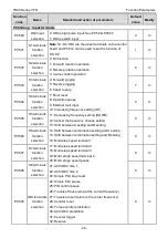
26: Establishment of DC bus voltage
27
–30: Reserved
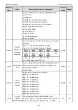
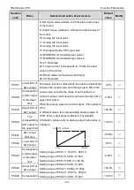
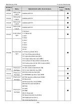
P06.05
Polarity
selection of
output
terminals
The function code is used to set the pole of the output
terminal.
When the current bit is set to 0, input terminal is positive.
When the current bit is set to 1, input terminal is
negative.
BIT3
BIT2
BIT1
BIT0
RO2
RO1
Reserved
Y1
Setting range: 0
–F
0
○
P06.06
Y1 open delay
time
The setting range: 0.000
–50.000s
0.000s
○
P06.07
Y1C off delay
time
The setting range: 0.000
–50.000s
0.000s
○
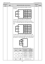
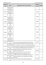
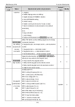
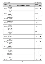
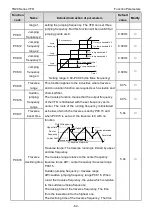
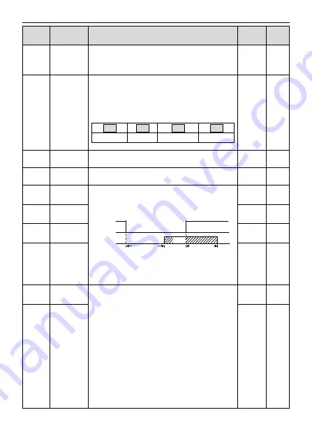
P06.10
RO1 switching
on delay time
The function code defines the corresponding delay time
of the electrical level change during the programmable
terminal switching on and off.
RO electrical level
RO valid
Invalid
Switch-on
delay
Invalid
Valid
Switch-off
delay
Setting range: 0.000
–50.000s
Note:
P06.08 and P06.08 are valid only when
P06.00=1.
0.000s
○
P06.11
RO1 switching
off delay time
0.000s
○
P06.12
RO2 switching
on delay time
0.000s
○
P06.13
RO2 switching
off delay time
0.000s
○
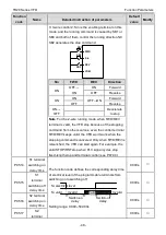
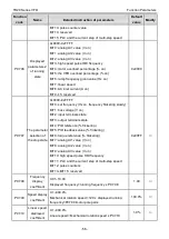
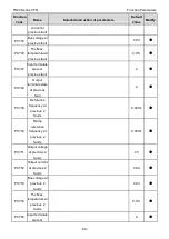
P06.14
AO1 output
selection
0: Running frequency
1: Setting frequency
2: Ramp reference frequency
3: Running rotation speed (relative to 2 times the
rotating speed of the motor)
4: Output current (relative to 2 times rated current of the
VFD)
5: Output current (relative to 2 times rated current of the
motor)
6: Output voltage (relative to 1.5 times the rated voltage
of the VFD)
7: Output power (relative to 2 times the rated power of
the motor)
0
○
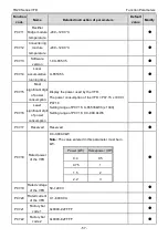
P06.15
AO2 output
selection
0
○
Содержание TD20 Series
Страница 1: ......
Страница 129: ...TD20 Series VFD Appendix C Peripheral Options and Parts 127 PB External brake resistor TD20...
Страница 131: ......


