2-4
2. MAIN UNIT REPLACEMENT
EO18-33002A
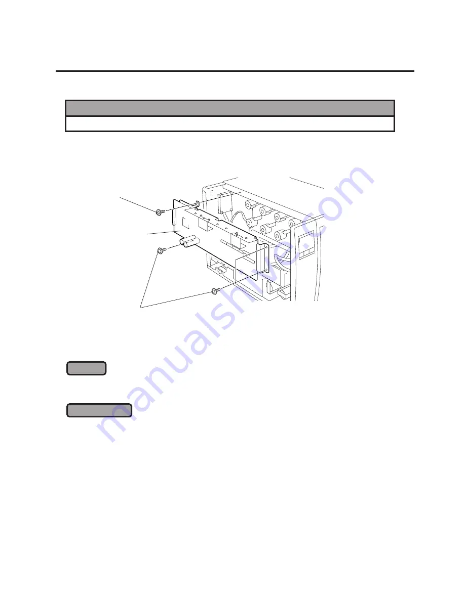
2.3 REPLACING THE DRIVER PC BOARD
1) Remove the CPU PC board. (See Section 2.1.)
2) Disconnect all connectors from the driver PC board.
3) Remove the four SMW-4x8 screws to detach the driver PC board from the printer.
4) After replacing the driver PC board with a new one, refer to the following [CHECK] and [ADJUSTMENT]
and reassemble in the reverse order of removal.
1.
Set the DIP switches on the new driver PC board. (Refer to Section 2.13.)
2.
Firmly connect the harnesses with the connectors by matching their colors on the driver PC board.
1.
After replacing the driver PC board, be sure to adjust the media sensor voltage following the
procedure described on the next page.
2.
Refer to the Owner’s Manual to readjust the media sensor sensitivity.
2.3 REPLACING THE DRIVER PC BOARD
CHECK
ADJUSTMENT
Fig. 2-4
SMW-4x8 Screw
SMW-4x8 Screw
WARNING!
Replace only with the same type and rated fuse for continued protection against risk of fire.
Driver PC Board


