background image

2-3

2. MAIN UNIT REPLACEMENT

EO18-33002A

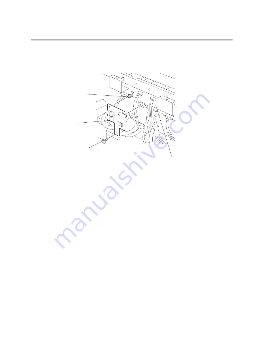
2.2 REPLACING THE HCHK PC BOARD

2.2 REPLACING THE HCHK PC BOARD

1) Remove the SMW-3x6 screw from the HCHK PC board.

2) Release the HCHK PC board from the locking support.

Locking Support

Fig. 2-3

3) Replace the HCHK PC board with a new one, and then reassemble in the reverse order of removal.

SMW-3x6 Screw

Driver PC Boared

HCHK PC Board

Содержание CB-416 Series

Страница 1: ...PRINTED IN JAPAN TEC Color Printer CB 416 426 T3 SERIES Original Aug 1998 Revised Mar 1999 Document No EO18 33002A Maintenance Manual...

Страница 2: ...CB 1204 QM 3 1 3 2 RIBBON MODULE CB 1004 QM 3 3 3 3 PRINT HEAD FAN 3 5 4 TROUBLESHOOTING 4 1 5 DIAG TEST OPERATION 5 1 5 1 OUTLINE OF THE DIAG TEST OPERATION 5 1 5 2 SELF TEST MODE 5 2 5 3 PARAMETER...

Страница 3: ...the printer and remove the side pads L and R 4 Place the printer on a level surface Media Side Black Screw Partition Supply Roll Holder Pad L Supply Roll Holder Supply Roll Holder Pad R Carton Carton...

Страница 4: ...printer the two print head blocks to the right hand are not installed Please accept that all illustrations provided in this manual hereafter are for the CB 416 T3 QQ QP 1 2 CHECKS 1 Check for damage o...

Страница 5: ...ication During parts replacement 2 Kinds of oil FLOIL G 488 1Kg can Part No 19454906001 3 Do not spray the inside of the printer with lubricants Unsuitable oil can damage the mechanism All machines ar...

Страница 6: ...2 d e e p s n o i s s i m s n a r T F F O F F O S P B 0 0 4 2 N O F F O S P B 0 0 8 4 F F O N O S P B 0 0 6 9 N O N O S P B 0 0 2 9 1 3 F F O t i b 1 h t g n e l t i b p o t S N O s t i b 2 4 F F O s...

Страница 7: ...THE HCHK PC BOARD 1 Remove the SMW 3x6 screw from the HCHK PC board 2 Release the HCHK PC board from the locking support Locking Support Fig 2 3 3 Replace the HCHK PC board with a new one and then re...

Страница 8: ...l 1 Set the DIP switches on the new driver PC board Refer to Section 2 13 2 Firmly connect the harnesses with the connectors by matching their colors on the driver PC board 1 After replacing the drive...

Страница 9: ...justment knob within the angle range of 150 degree to 210 degree and retry Feed Gap Sensor Fully turn the black mark sensor adjustment knob on the rear of the printer counterclockwise Turn the feed ga...

Страница 10: ...er PC board See Section 2 3 3 Disconnect all cables from the HWC PC board 4 Remove the three SMW 3x6 screws small washer type and two SMW 3x6 screws to detach the HWC PC board from the driver PC board...

Страница 11: ...sconnect all cables from the PDM PC board 2 Remove the four SMW 3x6 screws to detach the PDM PC board Fig 2 9 PDM PC Board 2 5 REPLACING THE PDM PC BOARD SMW 3x6 Screw SMW 3x6 Screw 3 Replace the PDM...

Страница 12: ...ction 3 Remove the N 3 nut and D 3x6 screw to remove the thermistor from the PS unit 4 Replace the PS unit with a new one and then reassemble in the reverse order of removal 2 6 REPLACING THE PS UNIT...

Страница 13: ...feed motors with new ones refer to the following LUBRICATION and CHECK and reassemble in the reverse order of removal Apply FLOIL G 488 to the surface of the gears 1 To allow sufficient backlash for...

Страница 14: ...s y with a new one refer to the following CHECK and ADJUSTMENT and reassemble in the reverse order of removal Install a new ribbon motor ass y so that the ribbon flange is centered with the hole on th...

Страница 15: ...fertothefollowing CHECK and ADJUSTMENT and reassemble in the reverse order of removal Be sure to fix the solenoid ass y cable in position with a cable band Solenoid installation method Install the rib...

Страница 16: ...Head Lock Lever Connector Red Screws Never remove them Print Head Print Head Falculum Shaft Print Head Fixing Plate Print Head Mechanism Fig 2 14 CAUTION 1 NEVER touch the element when handling the p...

Страница 17: ...der guide plate remove the eight SMW 3x10 nine SMW 4x8 and one SMW 3x6 screws to detach the under guide plate and the platen frame 7 Remove the washer and two platen holders to detach the platen 8 Dis...

Страница 18: ...auge 2 Refer to Adjusting the Media Sensor Voltage on page 2 5 to readjust the voltage NOTE The guide plate which differs in shape from other guide plates is to be installed nearest to the front of th...

Страница 19: ...itioned at the lower left of the driver PC board NOTES 1 Be sure to set the all switches of DIP SW 1 to OFF 2 OFF means OPEN 2 13 DIP SWITCH SETTINGS Fig 2 18 DIP SW 2 DIP switch 2 is located on the m...

Страница 20: ...near end status is sent to the PC Continues printing when the ribbon near end is detected The ribbon near end status is not sent to the PC Continues printing when the ribbon near end is detected The r...

Страница 21: ...Cutter Unit 1 Cutter Cover 1 Screw SMW 4x8 3 1 Open the top cover and remove the two B 4x6 screws to detach the front cover Refer to page 2 1 2 Connect the two connectors 3 Install the cutter unit in...

Страница 22: ...e fine adjusted refer to section 5 3 1 2 Adjust Cut Angle When the cutter cuts media obliquely follow the procedure below to adjust the cut angle 1 Loosen the two SMW 4x8 screws 2 Move the guide plate...

Страница 23: ...Fit the bosses on the sheet fixing plate into the holes of the ribbon tension sheet and the aluminum frame Secure them with the three D 3x5 screws The double sided adhesive tape does not need to be us...

Страница 24: ...n once again take up any ribbon slack 8 Close the top cover Fig 3 7 Fig 3 6 Notch Protrusion Ribbon Shaft Ribbon Feed Core Ribbon Stopper Ribbon Module Ribbon Winding Core Print Head Machanism Ribbon...

Страница 25: ...k pattern at a speed of 6 sec it may stop printing after about a 6 minute operation 1 Unplug the power cord 2 Remove the side panel L from the printer 3 Attach the print head fan to the print head fra...

Страница 26: ...ntact or broken wires 3 Failure in rewinding feeding of the ribbon 4 Failure of the driver PC board 5 Failure of the CPU PC board 6 Failure of the software 7 Failure of the printer cable 1 Broken prin...
Страница 27: ...7 42 27 1 18 38 Ifthetroubleisnotsolved replace the CPU PC board Replace the driver PC board Problems Blurred print Ribbon wrinkle Ribbon end error Label feed failure Print position misalignment Commu...

Страница 28: ...on print 5 30 5 3 4 Print Start Position Fine Adjustment Mode 5 32 5 3 5 Printer Parameter Setting Mode 5 33 5 3 5 1 Character code selection 5 33 5 3 5 2 Font zero selection 5 34 5 3 5 3 Control code...

Страница 29: ...tion as described below Key Function Table Revision Date Dec 20 2000 5 1 OUTLINE OF THE DIAG TEST OPERATION 5 DIAG TEST OPERATION 5 1 OUTLINE OF THE DIAG TEST OPERATION In system mode the diag test op...

Страница 30: ...ic Diagnostic Printing The data from 1 to 9 on a sample print is printed Power off Press the PAUSE key Press the PAUSE key Press the PAUSE key Select the sensor type from those at the right by pressin...

Страница 31: ...g to the software version of PROGRAM MASK ROM 2 The last two digits of the checksum are usually 0 2 KANJI ROM Check 1 PROGRAM MASK ROM Check 1 2 3 4 5 6 7 8 9 10 11 12 13 14 15 16 VERSION PARTS NO CHE...

Страница 32: ...table SIMM Image buffer memory or work memory MEMORY SIMM 16MB SLOT1 16MB SLOT2 0MB Total memory SIMM capacity on SLOT2 SIMM capacity on SLOT1 Image buffer memory or work memory 5 SIMM Memory Capacity...

Страница 33: ...rank of yellow print head A D value Resistance rank of black print head A D value Resistance rank of magenta print head A D value Resistance rank of cyan print head A D value 9 Print head resistance...

Страница 34: ...Home position 15 Slit sensor check CB 416 RIBBON MOTOR ENCODER REWIND A REWIND B SUPPLY A SUPPLY B BLACK 1 0 0 1 MAGENTA 0 0 1 1 Slit sensor 0 At the slit 1 Out of the slit CYAN 1 0 0 1 YELLOW 0 0 0...

Страница 35: ...a sample print is printed This data is the printer status and the value set in the parameter setting mode 5 2 SELF TEST MODE Power off Press the PAUSE key Press the PAUSE key Press the PAUSE key Selec...

Страница 36: ...ribbon save operation Up Down 2 count See NOTE 3 Counts when the ribbon motor drives to feed print and issue the media The driving time is not count during ribbon saving operation but is during back...

Страница 37: ...an Yellow CB 426 HEAD1 HEAD2 Ribbon feed motor voltage fine adjustment CB 416 Black Magenta Cyan Yellow CB 426 HEAD1 HEAD2 Character code selection Font zero selection Control code selection Remarks 3...

Страница 38: ...s the FEED key P O I T I O N S P R N T C O N D I T I O N I Press the FEED key P R N T D E N S I T Y I Press the FEED key H E D A D J U S T A Press the FEED key P R N T E R P A R A I Press the FEED key...

Страница 39: ...tting ADJUST Status print before X Y directions adjustment X DIRECTION X direction alignment fine adjustment Y DIRECTION Y direction alignment fine adjustment CHECK Adjustment value confirmation print...

Страница 40: ...length See NOTE 1 Press the FEED key and RESTART key at the same time Continued on Section 5 3 1 2 Cut Position Fine Adjustment Print start position fine adjustment Position adjustment mode display R...

Страница 41: ...RESTART key to adjust the feed length See NOTE 1 Press the FEED key and RESTART key at the same time Continued on Section 5 3 1 3 Reverse Feed Distance Fine Adjustment Cut position fine adjustment Po...

Страница 42: ...RESTART key to adjust the feed length See NOTE 1 Press the FEED key and RESTART key at the same time Continued on Section 5 3 1 4 Print Stop Position Fine Adjustment Reverse feed distance fine adjustm...

Страница 43: ...0 0 mm 10 0 mm 10 mm 10 mm Fig 5 3 Fig 5 4 Fig 5 5 0 0 mm Feed Direction 12 0 mm 12 0 mm Black Mark Cut Position Print Head Tag Paper Platen 12 mm 12 mm Fig 5 6 Fig 5 7 Fig 5 8 5 3 PARAMETER SETTING M...

Страница 44: ...5 DIAG TEST OPERATION 5 3 PARAMETER SETTING MODE A A A A A A A A A A A A 0 0 mm Feed Direction 3 0 mm 3 0 mm 3 0 mm 3 0 mm Print start position Fig 5 9 Fig 5 10 Fig 5 11 Reverse feed distance fine ad...

Страница 45: ...RESTART key to adjust the Print stop psition See NOTE 1 Press the FEED key and RESTART key at the same time Continued on Section 5 3 1 5 X Coordinate Fine Adjustment Print stop position fine adjustmen...

Страница 46: ...y five times P O I T I O N S X D J U S T 0 0 m m A Press the FEED or RESTART key to fine adjust the print position along the X coordinate See NOTE 1 X coordinate fine adjustment Position adjustment mo...

Страница 47: ...erformed to fine adjust the X coordinate of the drawing in the left or right direction 5 Adjust the X coordinate in the effective print range After the value reaches the coordinate 0 thevalueremainsun...

Страница 48: ...adjustment mode Press the FEED or RESTART key to adjust the print tone See NOTE 1 Press the PAUSE key Y E L O W 0 L Press the FEED or RESTART key to adjust the print tone See NOTE 1 Press the FEED or...

Страница 49: ...media back feeding P R N T S P E E D 6 S I Set print speed with the FEED or PAUSE key S E S O R T R A N S N Set the sensor type with the FEED or PAUSE key B A K F E E D Y E S C Select use or non use...

Страница 50: ...e PAUSE key Press FEED key A D U S T J P R N T C O N D I T I O N I 2 P A R A M E T E R S E T Press the PAUSE key Press PAUSE key Press the PAUSE key twice P O I T I O N S H E D A D J U S T A Print con...

Страница 51: ...during printing the error message is displayed and printing is stopped The error is cleared by pressing the PAUSE key and the display shows 2 PARAMETER SET Printing is not automatically resumed after...

Страница 52: ...isplay Skip Black s X direction fine adjustment Alphabet E F G or H Magenta s X direction fine adjustment value Alphabet Number 00 to 30 X direction fine adjustment display M A E N T A F 0 0 G Press t...

Страница 53: ...line indicated by 2 Read the scale of the position indicated by 3 4 Enterthealpha numericsobtainedinsteps1 through3 intotheHeadAdjustdisplay Inthiscase enter F7 5 The values for cyan and yellow are ob...

Страница 54: ...e a 2nd print head aligns with the black line indicated by 2 Read the scale of the position indicated by 3 4 Enterthealpha numericsobtainedinsteps1 through3 intotheHeadAdjustdisplay Inthiscase enter F...

Страница 55: ...ing display Skip Black s Y direction fine adjustment Alphabet A B C or D Magenta s Y direction fine adjustment value Number Number 00 to 30 Y direction fine adjustment display M A E N T A B 0 0 G Pres...

Страница 56: ...magenta is printed on the row A or B refer to the left print sample When row C or D refer to the right print sample 3 Check where a magenta aligns with the black line indicated by 5 Read the scale of...

Страница 57: ...ted on the row B When 2nd print head is printed on the row A or B refer to the left print sample When row C or D refer to the right print sample 3 Check where a 2nd print head aligns with the black li...

Страница 58: ...olding down the FEED key and PAUSE key 1 D I A G V 1 O A Designated number of labels are issued according to the print conditions set in Section 5 3 3 1 by pressing the PAUSE key Press the FEED key fo...

Страница 59: ...essage is displayed and printing is stopped The error is cleared by pressing the PAUSE key and the display shows 2 PARAMETER SET Printing is not automatically resumed after the error is cleared 2 Extr...

Страница 60: ...ff Press the FEED key Turn on the power while holding down the FEED key and PAUSE key 1 D I A G V 1 O A 2 P A R A M E T E R S E T Press the FEED key Press the FEED three times P O I T I O N S Press th...

Страница 61: ...D key four times P O I T I O N S Press the PAUSE key Printer parameter setting display Press the PAUSE key F O T C O D E P C 8 5 0 N P R N T E R P A R A I Select either character code with the FEED ke...

Страница 62: ...T I O N S Press PAUSE key twice Printer parameter setting display Z E O F O N T 0 R P R N T E R P A R A I Zero font selection 0 without slash 0 with slash Select either zero font with the FEED key or...

Страница 63: ...D P R N T E R P A R A I Control code selection AUTO Automatic selection Manual selection ESC LF NUL Manual selection Select control code with the FEED key or RESTART key See NOTE 1 Press the PAUSE key...

Страница 64: ...FEED or RESTART key to select the motor type Press the PAUSE key Continued on section 5 3 5 5 Euro Font Code Selection NOTES 1 Usually select AUTO for the pulse motor speed A color misalignment may o...

Страница 65: ...Press the PAUSE key Press the FEED key four times P O I T I O N S Press PAUSE key five time Printer parameter setting display E U O O D E B O R P R N T E R P A R A I Euro Font Code selection Press th...

Страница 66: ...ress the PAUSE key Press the PAUSE key Press the FEED key five time Press PAUSE key P O I T I O N S P M A D J 0 P M A D J Press the FEED or RESTART key to fine adjust the platen motor voltage See NOTE...

Страница 67: ...E D S E L E C T A Press the PAUSE key Color designation display ON Use OFF Not use MAGENTA CYAN YELLOW Repeat the above procedure to other print heads Select use or non use of each print head with the...

Страница 68: ...bon CR 30xxx P1S MAGENTA CYAN YELLOW Repeat the above procedure to other print heads Select the ribbon type with the FEED or RESTART key Press the FEED key and RESTART key at same time Press the PAUSE...

Страница 69: ...ssing the PAUSE key Power off Press the FEED key Turn on the power while holding down the FEED key and PAUSE key 1 D I A G V 1 O A 2 P A R A M E T E R S E T Press the PAUSE key Press the FEED eight ti...

Страница 70: ...without using the printer driver exclusively for the fine mode print could be shrunk in the vertical direction Power off Press the FEED key Turn on the power while holding down the FEED key and PAUSE...

Страница 71: ...PE Batch without cut LABEL LENGTH 102 mm PAPER FEED Feed Operating procedure for the test mode is provided below Power off Press the FEED key twice Turn on the power while holding down the FEED key an...

Страница 72: ...ESTART key See NOTE 2 and 4 Set the print speed P R N T S P E E D 6 s I Set the sensor type S E S O R T R A N S N Press the PAUSE key See NOTE 3 5000 Print count 5000 6 sec 4 sec 1000 Print count 1000...

Страница 73: ...E D Y E S C Press the PAUSE key See NOTE 3 To of the preceding page C Press the FEED key and RESTART key at the same time To of the preceding page C Press the FEED key and RESTART key at the same tim...

Страница 74: ...e preceding page C Press the FEED key and RESTART key at the same time 300 Label length 300 mm 299 Label length 299 mm 298 Label length 298 mm 12 Label length 12 mm 11 Label length 11 mm 10 Label leng...

Страница 75: ...GENTA C CYAN Y YELLOW Press the FEED key and RESTART key at the same time CB 416 1 1st print head 2 2nd print head CB 426 NOTES 1 When there is no change to the print condition select one of the test...

Страница 76: ...ot automatically resumed after the error is cleared 8 When AUTO PRINT is selected 3 pcs of the slant line labels color bar print labels and character labels are printed respectively after one label is...

Страница 77: ...mm Operating procedure for the test mode is provided below 5 4 TEST PRINT MODE Power off Press the FEED key twice Turn on the power while holding down the FEED key and PAUSE key 1 D I A G V 1 O A 3 T...

Страница 78: ...key A U O P R I N T T R A N T 3 T E S T P R I N T Characters are printed on 3 labels Press the PAUSE key Color bars are printed on 3 labels Press the PAUSE key A U O P R I N T T R A N T A U O P R I N...

Страница 79: ...gh the maintenance counter procedure in self test mode See NOTE 1 ITEM Total feed length Print distance CB 416 black CB 426 1st Print distance CB 416 magenta CB 426 2nd Print distance CB 416 cyan Prin...

Страница 80: ...djustment CB 416 black CB 426 1st KEY Print tone fine adjustment CB 416 magenta CB 426 2nd KEY Print tone fine adjustment CB 416 cyan KEY Print tone fine adjustment CB 416 yellow KEY X coordinate fine...

Страница 81: ...AUSE key 1 D I A G V 1 O A Turn off the power NOTE 1 C O P L E T E M 4 R A M C L E A R Press the PAUSE key Press the PAUSE key Press the FEED key and RESTART key at the same time Press the FEED key or...

Страница 82: ...and PAUSE key 1 D I A G V 1 O A Turn off the power NOTE 1 C O P L E T E M 4 R A M C L E A R Press the PAUSE key Press the PAUSE key Press the FEED key and RESTART key at the same time Press the FEED k...

Страница 83: ...Press the FEED key and RESTART key at the same time Press the FEED key three times or press the RESTART key Select the item to be cleared by pressing the FEED and RESTART keys Press the PAUSE key Pres...

Страница 84: ...am Loader Program Loader Setup Disk 1 and 2 in the PC 2 Copy the prog bin file in the Program Data Disk to the directory created in step 1 3 Set the DIP SW3 on the VR PC board to ON and turn the print...

Страница 85: ...ROCEDURE 2 Run the Setup exe in the Program Loader FDK 3 When the Program Loader has been installed the following message will appear NOTE Once the Program Loader has been installed it is not required...

Страница 86: ...T3 QQ QP Program Data DISK V1 0 28th August 1998 FMRM0048401 9200 D300 V001 000 The directory is created in the Program Files as a default 5 Set the DIP SW3 on the VR PC board to ON and then turn the...

Страница 87: ...lect Program for the Target Usually Boot program is not downloaded EO18 33002 Revision Date Jan 20 99 6 4 DOWNLOAD PROCEDURE 8 Click on the Start button to start the program download While the program...

Страница 88: ...nterface the program write onto the flash ROM has not been completed yet NOTE DO NOT turn the printer power off until COMPLETE is displayed on the LCD EO18 33002 Revision Date Jan 20 99 6 4 DOWNLOAD P...

Отзывы: