409-32023
Rev
B
7 of 41
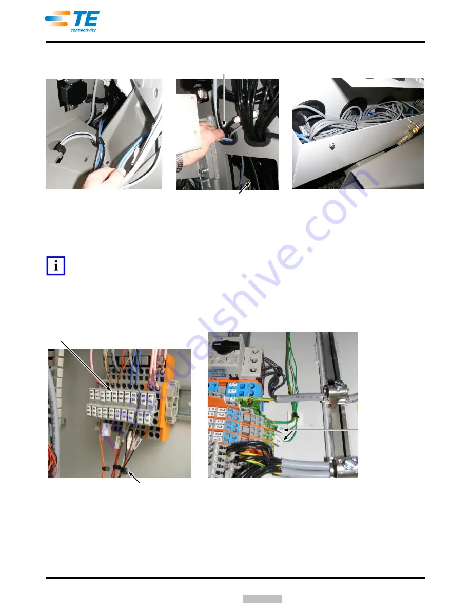
Figure 5
c. Remove the access cover, and run the cable into the machine. See Figure 5. Run the power cable
into the main electrical box. See Figure 6.
NOTE
Excess cable can be wire-tied and left in the wire way as shown in Figure 5.
d. Connect the power cable to the power block and machine ground as shown in Figure 6. Refer to
schematic 2161898 in documentation package 2161819.
The Ethernet communication cable is connected in the connection box as shown in Figure 7.
Figure 6
Power and Communication Cables
Routed Along Back Side of Terminator
Access Cover Removed
Cable Run Into Machine
Note
: Cover Removed for Clarity
Excess Cable in Wire Way
Power Block Located on Right Side
of Main Electrical Box
Ground Connections
on Bottom of
Electrical Cabinet
Power Cable
Downloaded From


