


Maintenance, Service, and Repair
Steering
Page 6
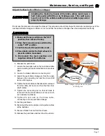
7. Disconnect the drag link from the pitman arm.
NOTE: Refer to
Replace the Ball Joints
section for information regarding
removing the ball joint from the drag link.
8. Loosen the gear lash jam nut and the worm bearing
adjuster jam nut.
9. Unscrew the gear lash adjuster all of the way to the
stop.
10. Loosen the worm bearing adjuster and then tighten
just enough to remove all end play from the input
shaft and then an additional 1/8 turn more.
11. While holding the worm bearing adjuster so that it
cannot turn, tighten the worm bearing adjuster jam
nut.
12. Find the center position of the steering shaft:
A. Turn the steering shaft all of the way in one direction.
B. While counting the rotations, turn the steering shaft all of the way in the opposite direction.
C. Turn the steering shaft 1/2 the number of turns in the original direction.
13. While rotating the input shaft back and forth through its centered position, adjust the gear lash
adjusting screw so that there is a slight drag as the steering gear is rotated through its centered
position.
14. While holding the gear lash adjusting screw so that it cannot turn, tighten the gear lash adjusting
screw jam nut.
15. Reconnect the main positive and negative cables at the batteries.
16. Remove the blocks from behind the wheels.
17. Release the parking brake and test drive the vehicle.
Содержание B 1-50
Страница 2: ......
Страница 6: ...TAYLOR DUNN ...
Страница 14: ...Model B 1 00 ...
Страница 30: ...TAYLOR DUNN ...
Страница 36: ...TAYLOR DUNN ...
Страница 52: ...TAYLOR DUNN ...
Страница 66: ...Maintenance Service and Repair Steering Page 14 Exploded View of Steering Gear ...
Страница 90: ...TAYLOR DUNN ...
Страница 124: ...TAYLOR DUNN ...
Страница 130: ...TAYLOR DUNN ...
Страница 161: ...Wire Diagrams ...
Страница 192: ...Illustrated Parts PARTS PAGE 8 Steering Gear 5 4 2 1 6 See steering linkage 7 10 15 17 3 11 12 13 14 16 ...
Страница 194: ...Illustrated Parts PARTS PAGE 10 Front Suspension 4 3 2 1 5 10 6 8 9 7 11 12 ...
Страница 200: ...Illustrated Parts PARTS PAGE 16 Rear Suspension 5 7 8 3 4 Ref Frame 2 6 4 1 Ref Transmission axle tube ...
Страница 202: ...Illustrated Parts PARTS PAGE 18 Motor 2 3 5 6 4 7 8 1 9 10 Armature 9 ...
Страница 206: ...Illustrated Parts PARTS PAGE 22 Wheels and Tires Ref wheel hub 1 2 5 assembly 4 3 6 7 8 9 ...
Страница 208: ...Illustrated Parts PARTS PAGE 24 Instrument Panel dash ...
Страница 214: ...Illustrated Parts PARTS PAGE 30 Charger Lestronic 1 2 3 4 8 7 5 6 11 BI_CHARGER W INTERLOCK DWG Charger Identification ...
Страница 217: ...Illustrated Parts PARTS PAGE 33 This page intentionaly left blank ...
Страница 220: ...Illustrated Parts PARTS PAGE 36 Seat Cushions Deck and Lights B 1 50 ...
Страница 222: ...Illustrated Parts PARTS PAGE 38 Seat Cushions Deck and Lights MX 1600 ...
Страница 224: ...Illustrated Parts PARTS PAGE 40 Decals B 1 50 VIEW FROM INSIDE OF COWL 1 2 3 4 5 6 7 8 9 ...
Страница 230: ...Illustrated Parts PARTS PAGE 46 Stake Sides B 1 50 1 2 3 4 5 6 7 8 ...


