


Curtis PMC Troubleshooting
Page 8
1. Make sure the key-switch is in the “OFF” position, then remove the key.
2. Place the forward-reverse switch in the center “OFF” position.
3. Set the park brake.
4. Place blocks under the front wheels to prevent vehicle movement.
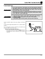
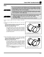
The rear drive wheels may rotate during some of the following tests. Block the
front wheels, raise the rear drive wheels off the ground, and support the vehicle
with jack stands. Failure to do so may cause the vehicle to move and cause
severe bodily injury and/or property damage.
Rotating rear drive wheels are a potential hazard. Keep hands, arms, legs and
loose clothing away from the rear drive wheels while conducting tests. Failure
to do so may cause serious bodily injury.
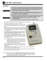
Power Wire Inputs
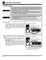
Connect a voltmeter to the PMC ‘B-’ terminal and battery
positive.
• If the voltage is not the same as battery volts then
there is an open circuit in the wire from ‘B-’ to the
battery. Stop troubleshooting here and repair the
problem. When the repair is completed, completely
retest the vehicle before lowering the drive wheels
to the ground.
B-
M-
A2
B+
#2
KSI
_
+
Main Battery Positive
The voltage shown is for illustration
only. The actual voltage may vary.
B-
M-
A2
B+
#2
KSI
_
+
The voltage shown is for illustration
only. The actual voltage may vary.
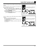
Connect a voltmeter across the PMC ‘B-’ terminal and the
PMC ‘B+’ terminal.
Close all interlock switches, turn the Key Switch ON,
and place the F&R Switch in Forward.
Depress the accelerator pedal to engage MS-1 only.
•
If the voltage is not the same as battery volts then
go to the
Solenoids
sequence.
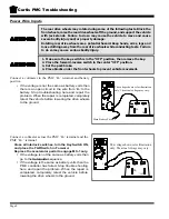
•
If the voltage is the same as battery volts then the
PMC controller has failed. Stop trouble shooting
here and repair the problem. When the repair is
completed, completely retest the vehicle before
lowering the drive wheels to the ground.
Содержание B 1-50
Страница 2: ......
Страница 6: ...TAYLOR DUNN ...
Страница 14: ...Model B 1 00 ...
Страница 30: ...TAYLOR DUNN ...
Страница 36: ...TAYLOR DUNN ...
Страница 52: ...TAYLOR DUNN ...
Страница 66: ...Maintenance Service and Repair Steering Page 14 Exploded View of Steering Gear ...
Страница 90: ...TAYLOR DUNN ...
Страница 124: ...TAYLOR DUNN ...
Страница 130: ...TAYLOR DUNN ...
Страница 161: ...Wire Diagrams ...
Страница 192: ...Illustrated Parts PARTS PAGE 8 Steering Gear 5 4 2 1 6 See steering linkage 7 10 15 17 3 11 12 13 14 16 ...
Страница 194: ...Illustrated Parts PARTS PAGE 10 Front Suspension 4 3 2 1 5 10 6 8 9 7 11 12 ...
Страница 200: ...Illustrated Parts PARTS PAGE 16 Rear Suspension 5 7 8 3 4 Ref Frame 2 6 4 1 Ref Transmission axle tube ...
Страница 202: ...Illustrated Parts PARTS PAGE 18 Motor 2 3 5 6 4 7 8 1 9 10 Armature 9 ...
Страница 206: ...Illustrated Parts PARTS PAGE 22 Wheels and Tires Ref wheel hub 1 2 5 assembly 4 3 6 7 8 9 ...
Страница 208: ...Illustrated Parts PARTS PAGE 24 Instrument Panel dash ...
Страница 214: ...Illustrated Parts PARTS PAGE 30 Charger Lestronic 1 2 3 4 8 7 5 6 11 BI_CHARGER W INTERLOCK DWG Charger Identification ...
Страница 217: ...Illustrated Parts PARTS PAGE 33 This page intentionaly left blank ...
Страница 220: ...Illustrated Parts PARTS PAGE 36 Seat Cushions Deck and Lights B 1 50 ...
Страница 222: ...Illustrated Parts PARTS PAGE 38 Seat Cushions Deck and Lights MX 1600 ...
Страница 224: ...Illustrated Parts PARTS PAGE 40 Decals B 1 50 VIEW FROM INSIDE OF COWL 1 2 3 4 5 6 7 8 9 ...
Страница 230: ...Illustrated Parts PARTS PAGE 46 Stake Sides B 1 50 1 2 3 4 5 6 7 8 ...