


Maintenance, Service, and Repair
Front Axle
Page 9
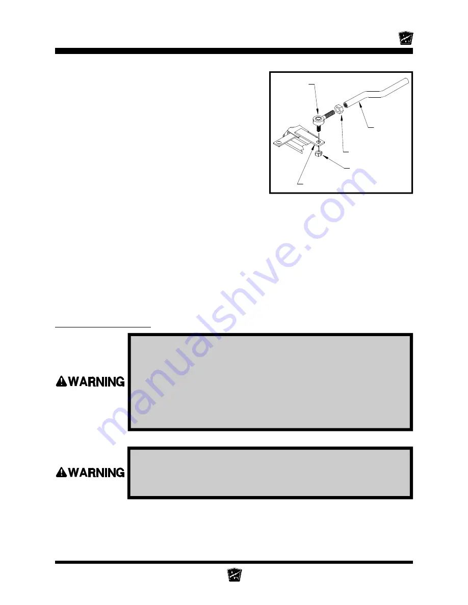
Rod End Nut
Rod End
Jam Nut
Steering
Sleeve
Steering Arm
1. Make sure the key-switch is in the “OFF” position, then remove
the key.
2. Place the forward-reverse switch in the center “OFF” position.
3. Set the park brake.
4. Place blocks under the rear wheels to prevent vehicle movement.
5. Disconnect the main positive and negative cables at the batteries.
Always use a lifting strap, hoist, and jack stands, of adequate capacity
to lift and support the vehicle. Failure to use lifting and support devices
of rated load capacity may result in severe bodily injury.
7. Loosen the rod end jam nut or clamp on the steering
sleeve.
8. Remove the rod end nut.
9. Remove the rod end from the steering arm.
HINT: Count the number of turns required to
remove the rod end from the steering
sleeve. This will make it easier to
realign the wheels.
10. Install the new rod end into the steering sleeve.
Screw it into the sleeve the same number of turns
counted in the previous step. Do not tighten the
rod end clamp or jam nut at this time.
11. Install the rod end into the steering arm. Tighten the rod end nut to 20-25 ft-lbs.
12. Realign the front wheels.
NOTE: Refer to the
Steering
section for information regarding realignment
of the front wheels.
13. Lower the vehicle.
14. Reconnect the main positive and negative cables at the batteries.
15. Remove the blocks from behind the wheels.
16. Release the park brake and test drive the vehicle.
Replacing a Ball Joint
6. Raise the front of the vehicle and support with jack stands.
Содержание B 1-50
Страница 2: ......
Страница 6: ...TAYLOR DUNN ...
Страница 14: ...Model B 1 00 ...
Страница 30: ...TAYLOR DUNN ...
Страница 36: ...TAYLOR DUNN ...
Страница 52: ...TAYLOR DUNN ...
Страница 66: ...Maintenance Service and Repair Steering Page 14 Exploded View of Steering Gear ...
Страница 90: ...TAYLOR DUNN ...
Страница 124: ...TAYLOR DUNN ...
Страница 130: ...TAYLOR DUNN ...
Страница 161: ...Wire Diagrams ...
Страница 192: ...Illustrated Parts PARTS PAGE 8 Steering Gear 5 4 2 1 6 See steering linkage 7 10 15 17 3 11 12 13 14 16 ...
Страница 194: ...Illustrated Parts PARTS PAGE 10 Front Suspension 4 3 2 1 5 10 6 8 9 7 11 12 ...
Страница 200: ...Illustrated Parts PARTS PAGE 16 Rear Suspension 5 7 8 3 4 Ref Frame 2 6 4 1 Ref Transmission axle tube ...
Страница 202: ...Illustrated Parts PARTS PAGE 18 Motor 2 3 5 6 4 7 8 1 9 10 Armature 9 ...
Страница 206: ...Illustrated Parts PARTS PAGE 22 Wheels and Tires Ref wheel hub 1 2 5 assembly 4 3 6 7 8 9 ...
Страница 208: ...Illustrated Parts PARTS PAGE 24 Instrument Panel dash ...
Страница 214: ...Illustrated Parts PARTS PAGE 30 Charger Lestronic 1 2 3 4 8 7 5 6 11 BI_CHARGER W INTERLOCK DWG Charger Identification ...
Страница 217: ...Illustrated Parts PARTS PAGE 33 This page intentionaly left blank ...
Страница 220: ...Illustrated Parts PARTS PAGE 36 Seat Cushions Deck and Lights B 1 50 ...
Страница 222: ...Illustrated Parts PARTS PAGE 38 Seat Cushions Deck and Lights MX 1600 ...
Страница 224: ...Illustrated Parts PARTS PAGE 40 Decals B 1 50 VIEW FROM INSIDE OF COWL 1 2 3 4 5 6 7 8 9 ...
Страница 230: ...Illustrated Parts PARTS PAGE 46 Stake Sides B 1 50 1 2 3 4 5 6 7 8 ...


