


Curtis PMC Troubleshooting
Page 22
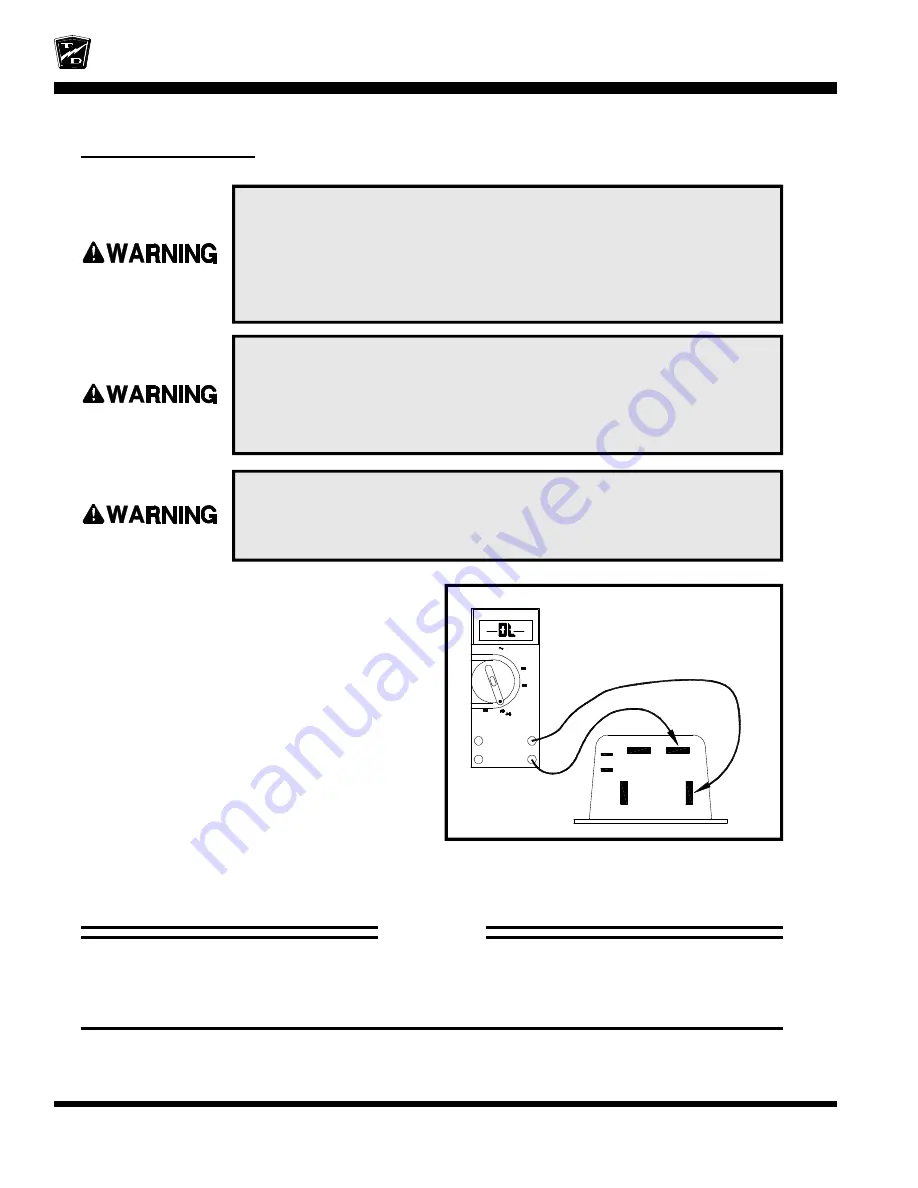
PLUGGING DIODE
Remove the wires from the ‘B+’ and ‘A2’
terminals on the PMC control and perform the
following test:
Using the diode test function on the DMM check
for the presence of a diode across ‘B+’ and ‘A2’
on the PMC control..
If you do not know how to test for a diode, refer
test to a qualified technician.
•
If the diode is open or shorted, then the
PMC control must be replaced. Stop
trouble shooting here and repair the
problem. When the repair is completed,
completely retest the vehicle before
lowering the drive wheels to the ground.
Ω
A
Hz
OFF
V
mV
V
SERIES II MULTIMETER
FLUKE 79
+
−
B
M
A2
B
#2
KSI
−
+
−
The reading shown is for illustration
only. The actual reading may vary.
STOP
Stop, do not continue. If you reached this point without a solution, then you may have an
unanticipated problem or have made an error during testing. It is important to review the
trouble shooting steps that have led to this point. The tests may need to be repeated.
1. Make sure the key-switch is in the “OFF” position, then remove
the key.
2. Place the forward-reverse switch in the center “OFF” position.
3. Set the park brake.
4. Place blocks under the front wheels to prevent vehicle movement.
5. Disconnect the main positive and negative cables at the batteries.
The rear drive wheels may rotate during some of the following tests.
Block the front wheels, raise the rear drive wheels off the ground,
and support the vehicle with jack stands. Failure to do so may cause
the vehicle to move and cause severe bodily injury and/or property
damage.
Rotating rear drive wheels are a potential hazard. Keep hands, arms,
legs and loose clothing away from the rear drive wheels while
conducting tests. Failure to do so may cause serious bodily injury.
Содержание B 1-50
Страница 2: ......
Страница 6: ...TAYLOR DUNN ...
Страница 14: ...Model B 1 00 ...
Страница 30: ...TAYLOR DUNN ...
Страница 36: ...TAYLOR DUNN ...
Страница 52: ...TAYLOR DUNN ...
Страница 66: ...Maintenance Service and Repair Steering Page 14 Exploded View of Steering Gear ...
Страница 90: ...TAYLOR DUNN ...
Страница 124: ...TAYLOR DUNN ...
Страница 130: ...TAYLOR DUNN ...
Страница 161: ...Wire Diagrams ...
Страница 192: ...Illustrated Parts PARTS PAGE 8 Steering Gear 5 4 2 1 6 See steering linkage 7 10 15 17 3 11 12 13 14 16 ...
Страница 194: ...Illustrated Parts PARTS PAGE 10 Front Suspension 4 3 2 1 5 10 6 8 9 7 11 12 ...
Страница 200: ...Illustrated Parts PARTS PAGE 16 Rear Suspension 5 7 8 3 4 Ref Frame 2 6 4 1 Ref Transmission axle tube ...
Страница 202: ...Illustrated Parts PARTS PAGE 18 Motor 2 3 5 6 4 7 8 1 9 10 Armature 9 ...
Страница 206: ...Illustrated Parts PARTS PAGE 22 Wheels and Tires Ref wheel hub 1 2 5 assembly 4 3 6 7 8 9 ...
Страница 208: ...Illustrated Parts PARTS PAGE 24 Instrument Panel dash ...
Страница 214: ...Illustrated Parts PARTS PAGE 30 Charger Lestronic 1 2 3 4 8 7 5 6 11 BI_CHARGER W INTERLOCK DWG Charger Identification ...
Страница 217: ...Illustrated Parts PARTS PAGE 33 This page intentionaly left blank ...
Страница 220: ...Illustrated Parts PARTS PAGE 36 Seat Cushions Deck and Lights B 1 50 ...
Страница 222: ...Illustrated Parts PARTS PAGE 38 Seat Cushions Deck and Lights MX 1600 ...
Страница 224: ...Illustrated Parts PARTS PAGE 40 Decals B 1 50 VIEW FROM INSIDE OF COWL 1 2 3 4 5 6 7 8 9 ...
Страница 230: ...Illustrated Parts PARTS PAGE 46 Stake Sides B 1 50 1 2 3 4 5 6 7 8 ...


