


Electrical Troubleshooting
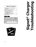
Charger Troubleshooting
Page 4
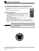
TEST EQUIPMENT REQUIRED FOR TROUBLESHOOTING
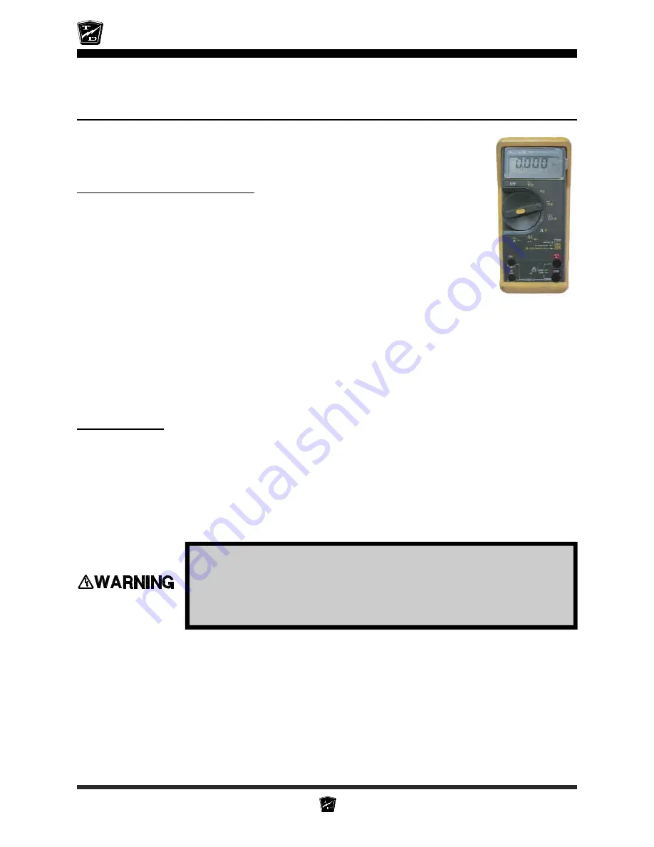
Digital Multi Meter (DMM) with diode and capacitor test function, FLUKE 79
®
model
shown at right and in the troubleshooting illustrations.
Important Notes and Instructions
• This troubleshooting guide assumes a familiarity with the use of a digital multimeter
including, voltage tests, continuity tests and diode testing. If not familiar with
any part of these tests, refer testing to a qualified technician.
• Make sure that the AC electrical socket the charger is plugged into is in good
working condition.
• Make sure that the AC voltage at the electrical socket is the same as the AC
voltage on the charger nameplate.
• Make sure the batteries are in good condition and no less than 80% discharged
as per hydrometer reading.
• The battery voltage must be above approximately 65% of the chargers rated DC voltage. If the batteries
are below approximately 65% of the chargers rated DC voltage, the charger will not turn on.
• If the charger exhibits intermittent problems, it must be in the failed mode for troubleshooting.
• Battery volts = Full voltage available at the batteries at the time of the test being performed.
• This test procedure must be performed in the order it was written. If starting in the middle or skipping
sections when not instructed to do so, the proper results will not occur. If the test result is good, then
proceed to the next test or go to the next section if instructed to do so.
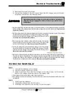
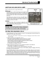
During All Tests
The charger cabinet must remain electrically grounded. Disconnect
both of the battery leads and unplug the charger from the AC source
before disconnecting any electrical component or wire. Failure to do
so may result in serious bodily injury.
Содержание B 1-50
Страница 2: ......
Страница 6: ...TAYLOR DUNN ...
Страница 14: ...Model B 1 00 ...
Страница 30: ...TAYLOR DUNN ...
Страница 36: ...TAYLOR DUNN ...
Страница 52: ...TAYLOR DUNN ...
Страница 66: ...Maintenance Service and Repair Steering Page 14 Exploded View of Steering Gear ...
Страница 90: ...TAYLOR DUNN ...
Страница 124: ...TAYLOR DUNN ...
Страница 130: ...TAYLOR DUNN ...
Страница 161: ...Wire Diagrams ...
Страница 192: ...Illustrated Parts PARTS PAGE 8 Steering Gear 5 4 2 1 6 See steering linkage 7 10 15 17 3 11 12 13 14 16 ...
Страница 194: ...Illustrated Parts PARTS PAGE 10 Front Suspension 4 3 2 1 5 10 6 8 9 7 11 12 ...
Страница 200: ...Illustrated Parts PARTS PAGE 16 Rear Suspension 5 7 8 3 4 Ref Frame 2 6 4 1 Ref Transmission axle tube ...
Страница 202: ...Illustrated Parts PARTS PAGE 18 Motor 2 3 5 6 4 7 8 1 9 10 Armature 9 ...
Страница 206: ...Illustrated Parts PARTS PAGE 22 Wheels and Tires Ref wheel hub 1 2 5 assembly 4 3 6 7 8 9 ...
Страница 208: ...Illustrated Parts PARTS PAGE 24 Instrument Panel dash ...
Страница 214: ...Illustrated Parts PARTS PAGE 30 Charger Lestronic 1 2 3 4 8 7 5 6 11 BI_CHARGER W INTERLOCK DWG Charger Identification ...
Страница 217: ...Illustrated Parts PARTS PAGE 33 This page intentionaly left blank ...
Страница 220: ...Illustrated Parts PARTS PAGE 36 Seat Cushions Deck and Lights B 1 50 ...
Страница 222: ...Illustrated Parts PARTS PAGE 38 Seat Cushions Deck and Lights MX 1600 ...
Страница 224: ...Illustrated Parts PARTS PAGE 40 Decals B 1 50 VIEW FROM INSIDE OF COWL 1 2 3 4 5 6 7 8 9 ...
Страница 230: ...Illustrated Parts PARTS PAGE 46 Stake Sides B 1 50 1 2 3 4 5 6 7 8 ...


