TASCAM DA-6400/DA-6400dp
13
2 – Names and Functions of Parts
7
Remaining media capacity
This shows the remaining available recording time of the
current media.
No Media
is shown when no SSD/HDD drive is loaded.
UNFORMAT
is shown if the loaded SSD/HDD drive has not
been formatted.
Rec Limit
is shown if recording is not possible because
the total number of folders, takes inside folders and other
files would exceed the system limit.
8
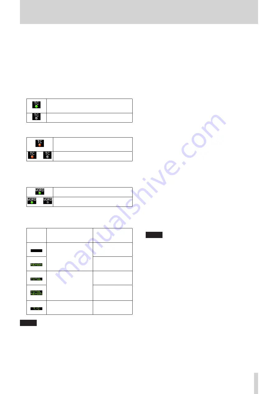
Timecode status
When the
TC GENERATOR MODE
screen is not set to
TC SYNC REC
.
The TC indicator lights green when correct
timecode is being input and recognized
properly.
The indicator does not light when input
timecode recognition is abnormal.
When the
TC GENERATOR MODE
screen is set to
TC
SYNC REC
.
The TC indicator lights red when correct
timecode is being input and recognized
properly.
§
The indicator flashes red when input
timecode recognition is abnormal.
9
Audio synchronization status
The name of the currently selected master clock is shown
with the indicator. (See “Setting the master clock” on page
When synchronized with the master clock,
the indicator lights green.
§
When not synchronized with the master
clock, the indicator blinks.
0
Time bar
This shows the current playback position. What is shown
depends on the time display mode.
Time
display
mode
Meaning
Bar display
The current playback
position is shown relative
to the length of the take.
Lengthens from the
left end toward the
right end.
Shortens from the left
end toward the right
end.
The current playback
position is shown relative
to the length of all takes
in the folder.
(Vertical white lines show
divisions between takes.)
Lengthens from the
left end toward the
right end.
Shortens from the left
end toward the right
end.
The current playback
position is shown relative
to the length of the take.
Lengthens from the
left end toward the
right end.
NOTE
During recording, a progress bar appears to extend from the
left end to the right end about every 10 seconds.
q
Take name
This shows the name of the currently loaded take.
w
Level meter display area
This area shows the levels of the input and playback signals.
When a level overloads, the bar meter becomes red and the
channel number appears in a pop-up above it.
e
Solo selection frame
The level meter for the channel currently output from the
PHONES
jack is shown with a white or gray frame. When the
selection frame appears white, turn the
MULTI JOG
dial to
select the channel output from the
PHONES
jack.
Press the
MULTI JOG
dial while pressing and holding
the
SHIFT
button to switch the headphone output solo
selection frame to white/gray.
When the
PHONES MONITOR MODE
screen setting is
MONO, the solo selection frame will be for a mono channel.
(See “Setting headphones monitoring mode” on page 20.)
r
Record function indicators
These show whether recording is enabled or not for each
channel.
Recording enabled: Red
Recording disabled: Gray
t
Marks
An
b
icon is shown at each mark.
y
Mark name
This shows the name of the mark at or immediately before
the current time.
u
Level meter guide
This level meter guide can be used to evaluate input and
output levels.
This line is shown at −18 dB.
The position of the guide and the value (
t
18
g
) shown
depend on the value set on the
REFERENCE LEVEL
screen. (See “Setting the reference level” on page 23.)
i
Input monitoring indicator area
These show whether input monitoring is enabled or not for
each channel.
Input monitoring on: Blue
Input monitoring off: Unlit
NOTE
When the sampling frequency is 88.2/96 kHz, the following
data in the area for channels 33–64 is not shown.
i
Level meters
i
Record function indicators
i
Input monitoring indicators
Furthermore, the solo selection frame cannot be moved to
channels 33–64.


