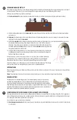
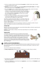
background image

15

SENSOR RANGE SETUP

The sensor range is factory set at the mouting surface of the faucet. Normally, this range setting does not need 
to be adjusted. If necessary, you can change the range setting at any time following these steps:

 (Please read all the steps before starting)
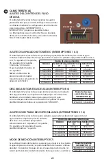
1.  Push and hold

 the blue button located at the front  of the control box. Water will start to fl ow.

ES

EN

2.  After holding the button for 

5 seconds

, the water fl ow will stop and the red LED next to the blue button 

will turn on. 

3. Release

 the blue button. The red LED will turn off  indicating that the sensor is ready to measure the new 

distance for the next 

15 seconds

4. Within 

5 seconds

 after releasing the blue button, hold any fl at object (or your hand) under the sensor at 

the desired distance. Keep the object still with in ±½ inch of the desired 
distance. Once the sensor detects a constant distance from the object, the 
red LED will fl ash 

5 times

 then remain on for 

2 seconds 

indicating the new 

range has been set and stored.

5. Confi rm the setting distance is correct placing a fl at object (or your hand) 

at diff erent distances and checking it does not turn on when the object is 
farther that the set distance. 

If the distance can’t be measure within 15 seconds, the red LED will blink 
quickly then stop, indicating the range setting will remain unchanged. 
Check that the sensor lens is clean and repeat the process from step 1. 

Once the range is set, the value is stored in the controller memory. The range 
will not be erased or changed by AC power loss or dead batteries.  
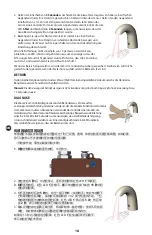
OPERATION

Place hands under spout. Water will fl ow until a set time limit is reached or the user’s hands are removed from 
sensor range.

Note:

 The activation time is less than 0.2 seconds but can be up to 1.5 seconds after a long time of inactivity.

DIAGNOSTICS

The WaveCrest controller diagnostics can detect battery status, AC power loss, 
performance degradation or any condition that prevents the faucet working 
correctly. In these situations, the controller will use the red LED to communicate 
that the faucet needs attention. For example, a single red LED fl ash every 2 seconds 
indicates the batteries are low and will need to be replaced soon. A constant red 
LED and no water fl ow indicates batteries are dead.

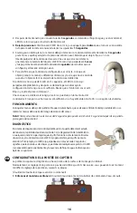
CONFIGURACIÓN DEL RANGO DE ALCANCE DEL SENSOR

El rango de alcance del sensor está confi gurado de fábrica a la superfi cie de montaje del grifo. Por lo general, 
esta confi guración del rango no se debe ajustar. Si fuera necesario, puede cambiar la confi guración del rango 
en cualquier momento siguiendo estos pasos:

 (Lea todos los pasos antes de comenzar)

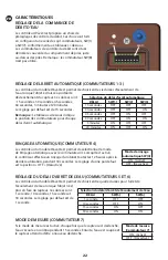
1. Mantenga presionado 

el botón azul que se localiza en la parte delantera de la caja de control. Comenzará 

a salir agua.

Содержание WaveCrest ECW-3150 Series

Страница 1: ...emedy for Breach of Contract which might arise is hereby excluded and disclaimed Any implied warranties of merchantability or fitness for a particular purpose are limited to three years in duration Un...

Страница 2: ...2 Exploded View ECW 3150 AND ECW 3160 SERIES 1 2 3 4 5 10 9 7 8 6...

Страница 3: ...3 Exploded View ECW 3170 SERIES 1 2 3 4 5 10 9 7 8 6...

Страница 4: ...45 8 A C Adapter 5EF 0002C 9 Supply Hose 9 16 24 UN Female x 1 2 NPSM 5EF 0005 10 Temperature Mixing Valve 5EF 0006 ECW 3170 Series Faucets 1 Curved Hidden Sensor with Screw 020755 45 2 0 5 GPM Hidden...

Страница 5: ...L GRIFO A LOS PAROS DEL SUMINISTRO Important TOUT LE C BLAGE LECTRIQUE DOIT TRE INSTALL CONFORM MENT AUX CODES ET R GLEMENTATIONS NATIONAUX LOCAUX TOUTE LA PLOMBERIE DOIT TRE INSTALL E CONFORM MENT AU...

Страница 6: ...lle o lave el lavabo Purgue la l nea L neas de suministro de agua caliente y fr a Tools Required For Installation of Faucets 8 200mm adjustable wrench Pliers 1 8 hex key wrench Phillips head screwdriv...

Страница 7: ...a mezcladora Instale la unidad del grifo Figuras 2A 2B y 2C Inserte el cable del grifo y el v stago de suministro a trav s de la junta de la base y despu s a trav s del orificio de montaje del fregade...

Страница 8: ...2B et 2C Ins rez le c ble du robinet et la tige du bec dans le joint de base puis au travers du trou de fixation de l vier de chirurgien ou de lavage Fixer l aide de la rondelle frein et de l crou fou...

Страница 9: ...uperficie de montaje de acero inoxidable Instale el grifo alineando el pasador con el orificio peque o Ensamble con la tuerca y la arandela para fijar el grifo en su sitio Nota Si no se necesita se pu...

Страница 10: ...dule as shown in Figure 3 Tighten fitting snugly BUT DO NOT OVERTIGHTEN No thread sealant is necessary Important Orient mixing valve as shown in Figure 3 Instale la unidad de la v lvula mezcladora Fig...

Страница 11: ...ura en las l neas de suministro Fixez le module de commande sur le mur Installez le module de commande un endroit appropri Une fois install tous les c bles et tuyaux souples doivent avoir un peu de je...

Страница 12: ...las l neas de suministro pero sin apretar en exceso Branchements du c ble du capteur et de la conduite d arriv e d eau Figure 4 Acheminez le c ble du capteur depuis la base du robinet jusqu au sommet...

Страница 13: ...been completed This type of adapter is designed to be plugged into a 120 VAC wall receptacle The AC adapter is supplied with a 6 foot cable Remove the rubber plug from the DC power connector on the bo...

Страница 14: ...Remarque Pour l option d alimentation Hydro Generator consultez le manuel d utilisation dans le kit EC HYDROGEN command s par ment Pour le c blage et les options de raccordement d alimentation c bl e...

Страница 15: ...blink quickly then stop indicating the range setting will remain unchanged Check that the sensor lens is clean and repeat the process from step 1 Once the range is set the value is stored in the cont...

Страница 16: ...valor se guardar en la memoria del controlador El rango no se borrar ni se modificar si no hay alimentaci n de CA o si se agotan las bater as FUNCIONAMIENTO Coloque las manos debajo del surtidor El ag...

Страница 17: ...g es UTILISATION Placez les mains sous le bec L eau s coule jusqu ce qu une limite de temps d finie soit atteinte ou que les mains de l utilisateur soient hors de port e du capteur Remarque Led laid a...

Страница 18: ...ist und wiederholen Sie den Ablauf ab Schritt 1 Wenn der Bereich eingestellt ist wird der Wert im Controllerspeicher gespeichert Der Bereich wird nicht gel scht oder ge ndert wenn der Netzstrom ausf...

Страница 19: ...NETTOYAGE DU CHROME ET DES FINITIONS SP CIALES N UTILISEZ aucun produit abrasif ou chimique m me de l eau de Javel pour nettoyer les robinets car ces produits peuvent endommager le lustre et attaquer...

Страница 20: ...switches SW 1 to SW 7 according to the tables below The flow control switches are located behind the battery cover just above the batteries Note SW 8 is not used PERIOD 15 seconds 30 seconds 45 secon...

Страница 21: ...del interruptor requeridas para cada per odo de apagado autom tico INTERRUPTOR 1 INTERRUPTOR 7 AJUSTE DEL RETRASO DE CORTE DEL AGUA INTERRUPTORES 5 Y 6 El controlador WaveCrest ofrece cuatro per odos...

Страница 22: ...de contr le du d bit sont situ s derri re le couvercle du compartiment de piles juste au dessus des piles Remarque le commutateur SW 8 n est pas utilis R GLAGE DE L ARR T AUTOMATIQUE COMMUTATEURS 1 3...

Страница 23: ...s in Schalterstellung 4 zu w hlen Wenn dieser aktiviert ist sp lt der Controller die Armatur nach der letzten Verwendung alle 12 Stunden 30 Sekunden lang Ab Werk steht der Schalter auf Off Aus SW 1 SW...

Страница 24: ...24 5 6 WaveCrest 1 10 15 30 1 7 15 SW 5 SW 6 1 10 15 30 SW 7 Wavecrest SW 1 SW 7 SW 8 1 3 Wavecrest 15 30 45 60 3 20 15 4 WaveCrest 4 12 30 off SW 1 SW 7 SW 4 SW 1 SW 2 SW 3 15 30 45 60 3 20 CN...

Страница 25: ...recuencia de exploraci n hasta su velocidad normal de detecci n SISTEMA ANTINTERFERENCIA La luz solar u otros tipos de iluminaci n pueden interferir con el rango de detecci n de la distancia El sensor...

Страница 26: ...ean Use only mild soaps and water Wipe with a soft cloth Preguntas y respuestas P Puede operarse el grifo manualmente sin usar el ojo electr nico R S Presione el bot n azul su ltelo y el agua comenzar...

Страница 27: ...t can contribute to the range for example bright lights highly reflective surfaces sunlight etc 1 Clean sensor lens 2 Range too long decrease detection zone Continues to Run Even after power to faucet...

Страница 28: ...l problema El rango del sensor es muy largo detecta el lavabo Reduzca el rango El detector est averiado se debe cambiar el m dulo del sensor 1 Revise los paros del suministro bralos si est n cerrados...

Страница 29: ...toyez la lentille du capteur 2 La port e est trop longue r duisez la zone de d tection L eau continue s couler M me apr s la mise hors tension du robinet 1 Des d bris bloquent l lectrovanne qui ne se...

Страница 30: ...ie zur Reichweite beitragen k nnen z B helle Lichter stark reflektierende Oberfl chen Sonnenlicht usw 1 Reinigen Sie die Sensorlinse 2 Reichweite zu lang Erfassungsbereich verringern L uft weiter Selb...

Страница 31: ...avelers Rest SC 29690 De Veenhoeve Phone 864 834 4102 Oude Nieuwveenseweg 84 Fax 864 834 3518 2441 CW Nieuwveen E mail tsbrass tsbrass com The Netherlands EC 3130 ChekPoint Above Deck Electronic Fauce...

Отзывы: