background image

INSTRUCTION

MANUAL

28

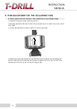
9. FINE ADJUSTMENT OF THE COLLARING TOOL

To obtain appropriate joint clearance a fine adjustment is occasionally needed.

1. Extend forming pins to the collaring position.
2. Note the position of the hash mark on the cylindrical cover in relation to a mark on the 

cover plate.
3. Loosen the adjustment screws a half turn on the cover plate.

4. Rotate the cover plate relative to the cylindrical cover clockwise for increasing and 

counter-clockwise for decreasing the diameter of adjustment. One notch on the cover 

plate equals to 0.5mm / 0.02” on the forming pin span.

Содержание PLUS 115 SS:

Страница 1: ...S 80 INSTRUCTION MANUAL SPARE PARTS LIST PORTABLE COLLARING SYSTEM FOR STAINLESS STEEL BRANCHING PLUS 115 SS...

Страница 2: ...y other language without a written permission of T DRILL Oy Is has been our aim to elaborate this instruction book with the greatest possible care and attention The accuracy of the in formation has be...

Страница 3: ...16 7 2 1 Assembly of the milling pin to the spindle 16 7 2 2 Chucking of the milling pin spindle 16 7 2 3 Removal of the milling pin spindle 16 7 3 Foot pedal 17 7 3 1 Detachment and attachment of th...

Страница 4: ...dle 5700301 58 15 10 Transport box 5700303 59 15 11 Transport box 5700304 60 15 12 Locking lever 5290206 A 61 15 13 Tool set 5700317 62 15 14 Pedal kit EU 5700320 63 15 15 Pedal kit US 5700321 63 15 1...

Страница 5: ...t been taken LDANGER Will or may cause a serious accident or death if the right precautionary measures have not been taken This instruction manual includes instructions for set up operation and mainte...

Страница 6: ...inflammations 2 GENERAL SAFETY INSTRUCTIONS Read all the instructions before using the machine Know your power tool Read the instruction manual carefully Learn to know your own skill and limitations a...

Страница 7: ...instructions for lubricating and changing accessories Inspect tool cords periodically and if damaged have them repaired by authorized service workshop Inspect extension cords periodically and replace...

Страница 8: ...t to leave your fingers between the machine and the tube When handling the tools be careful with the cutting blades Use protective gloves A falling machine or tool may damage your feet Use protective...

Страница 9: ...ies and limitations of this special tool The PLUS 115 must be used with the T DRILL T 65 grounded power tool with it s own connecting cord and a foot pedal for controlling of the T 65 This is because...

Страница 10: ...ng on the accessories between 65 kg and 75 kg PLUS 115 transport boxes and top shelf Storage Storing of T Drill machines and tools Clean machines tools and parts from lubricant chips and other debris...

Страница 11: ...speed turn the selector knob 180 When the selector is as shown in the picture the slow speed is switched on Slow speed I is used for forming of the outlet and trimming High speed II is for drilling If...

Страница 12: ...PARTS OF THE PLUS 115 1 2 5 6 8 9 11 3 4 10 7 1 Lead screw 2 Collaring head not visible 3 PLUS 115 unit 4 Base plate 5 Ring clamps 6 T 65 machine 7 Drilling unit 8 Lubricant 9 Elliptic pilot hole devi...

Страница 13: ...ocking lever 7 Ellipse pilot hole operation nut 2 Milling pin 8 Scale locking screw for A scale 3 Milling pin locking screws 3 pcs 9 Scale adjustment for A scale 4 Milling spindle 10 Scale adjustment...

Страница 14: ...collaring head may overload the tool 6 LUBRICATION Lubrication of the collaring head is essential to prevent overloading tool Lubrication also reduces wear on the collaring heads and hole drill and i...

Страница 15: ...the rated voltage specified on the tool 7 1 ASSEMBLY OF THE PLUS 115 DRILLING UNIT TO T 65 1 2 3 5 4 Drilling unit and T 65 1 T 65 machine 2 Push rods of the T 65 3 Drilling unit of PLUS 115 4 Attachm...

Страница 16: ...o insert the T DRILL milling pin spindle into the chuck rotate the locking ring 1 clockwise and slide the spindle shaft into the chuck Release the locking ring Rotate the T DRILL milling pin spindle 2...

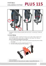
Страница 17: ...drives the ellipse device and the other is required for lubricating of the milling pin How to connect the foot pedal and T 65 machine 1 Secure the T 65 power trigger to ON position with lock ring enc...

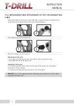
Страница 18: ...d 2 1 The American type of connecting cord Detachment of the cord 1 Turn the nut of the cord 1 2 turn to the left in order to loosen the cord 2 Draw the cord out of the power unit Attachment of the co...

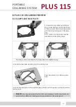
Страница 19: ...ring clamps must be assembled into the outer groove The clamps can be assembled to the base plate in two different ways 2 Clamp the base plate assembly over the collaring area 1 Place the pointer 1 t...

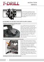
Страница 20: ...line as the desired dimension and tightening the screw The best size of the milling pin is proved to be 11 3mm Note the scale only reads 10 and 20 start with 10 and test Attaching the elliptic pilot h...

Страница 21: ...e machine allows the ellipse to run only in one direction First you need to turn the ellipse rotation nut counterclockwise so that the adjustment scale is parallel to the tube This to ensure that the...

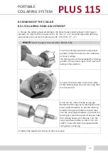
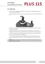
Страница 22: ...e Clean metal chips from the tube before collaring 8 2 1 INTERRUPTION OF PILOT HOLE MILLING If the pilot hole milling process is interrupted for example because of pin breakage do not restart milling...

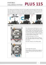
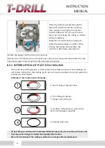
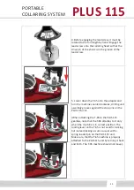
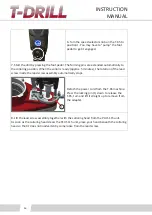
Страница 23: ...rming pins will be extended to collaring position You can hear a light click sound of locking in this position 3 Loosen the set screws on the cover plate of the collaring head one half tum using the 4...

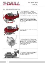
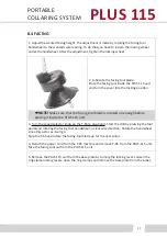
Страница 24: ...90 increments so you have four different collaring positions available to the same point 1 Turn the locking lever 1 to lock the PLUS 115 unit to base plate 2 Lubricate the forming pins of the collarin...

Страница 25: ...e counterclockwise drilling unit assembly grooves against the stop pins on the PLUS 115 unit When attaching the T 65 to the PLUS 115 gearbox note that the T 65 attaches to it only when the machine is...

Страница 26: ...tes the rotation of the lead screw inside the lead screw assembly automatically stops 1 Detach the power cord from the T 65 machine Press the locking pin 1 down to release the T 65 tum and lift it str...

Страница 27: ...is rotated up enough before placing it inside the PLUS 115 unit 3 Turn the speed selector knob on the T 65 to position II Start the drill by pressing the foot pedal and rotating the facing tool handwh...

Страница 28: ...2 Note the position of the hash mark on the cylindrical cover in relation to a mark on the cover plate 3 Loosen the adjustment screws a half turn on the cover plate 4 Rotate the cover plate relative...

Страница 29: ...Remove the plug from the end of the lead screw and put the 14 mm hex wrench through the hole of the lead screw and into the screw at the end of the collaring head 4 Turn the hex wrench counter clockw...

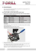
Страница 30: ...26 9 head 6310554 Drill 15 8 TiAlN For 33 7 and 42 4 heads 6310555 Drill 17 3 TiAlN For 48 3 head 6310722 Drill 19 0 TiAlN For 48 3 head Maintenance Keep the device clean wipe off all metal chips and...

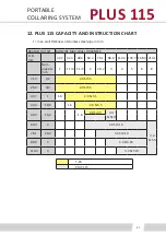
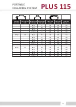
Страница 31: ...PE MAX WALL THICKNESS O D mm 33 7 42 4 48 3 60 3 76 1 88 9 114 3 139 7 168 3 219 1 Nom pipesize inch 1 1 1 4 1 1 2 2 2 1 2 3 4 5 6 8 21 3 1 2 2 0 Sch 5 26 9 3 4 2 0 Sch 5 33 7 1 1 6 2 0 Sch 5 42 4 1 1...

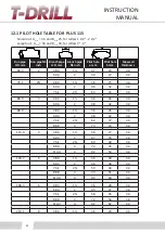
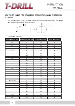
Страница 32: ...23 3 4 60 3 2 49 27 3 4 76 1 2 48 3 1 36 25 3 4 60 3 2 46 32 3 4 76 1 2 63 35 3 4 88 9 3 48 3 1 36 26 3 4 60 3 2 48 32 3 4 88 9 48 3 1 36 26 3 4 60 3 2 48 32 3 4 76 1 2 62 37 3 4 88 9 3 73 43 3 4 114...

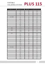
Страница 33: ...ilot hole a mm Pilot hole b mm Max wall thickness s 60 3 2 42 38 3 4 76 1 2 56 46 3 4 88 9 3 67 53 3 4 114 3 4 89 66 3 4 273 0 10 48 3 1 36 29 3 4 60 3 2 42 38 3 4 76 1 2 55 47 3 4 88 9 3 65 53 3 4 11...

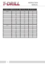
Страница 34: ...ell as on the condition of the tool used 1 Run tube 2 Branch Run pipe O D mm Branch pipe O D mm Pilot hole a mm Pilot hole b mm 51 51 40 25 57 51 40 25 57 46 25 63 5 51 40 25 57 46 27 63 5 52 28 70 51...

Страница 35: ...84 70 38 104 108 51 39 28 57 45 31 63 5 50 33 70 56 36 76 61 40 80 66 42 82 5 68 43 84 70 44 104 104 88 48 108 104 88 50 108 91 50 133 51 38 30 57 44 34 63 5 49 36 70 56 40 76 61 43 80 66 45 82 5 68 4...

Страница 36: ...ipe O D mm Pilot hole a mm Pilot hole b mm 193 7 51 38 31 57 43 35 63 5 49 39 70 55 44 76 60 47 80 65 49 82 5 67 50 84 69 51 104 88 62 108 91 63 219 1 51 38 31 57 44 35 63 5 48 38 70 55 43 76 61 47 80...

Страница 37: ...Product in question In no event shall the Customer have a right to return any Product without the prior written consent of T Drill The Customer acknowledges and agrees that the provisions of this war...

Страница 38: ...ILABILITY STOPPAGE OF OTHER WORK OR IMPAIRMENT OF OTHER ASSETS ARISING OUT OF BREACH OR FAILURE OF EXPRESS OR IMPLIED WARRANTIES BREACH OF CONTRACT MISREPRESENTATION NEGLIGENCE STRICT LIABILITY IN TOR...

Страница 39: ...Item Part No Name Size Type Std Manuf Qty 1 3500903 Clamp frame 2 2 3500904 Fastening plate 2 3 9214010 Screw M8 x 25 8 8 DIN7984 8 4 9016007 Set screw M8 x 8 12 9 DIN913 4 5 4280104 Clamp holder pin...

Страница 40: ...e 1 4 5700288 Pilot hole cutter 1 5 5700293 Drilling unit 1 6 5700301 Spindle 1 7 5700303 Transport box 1 8 5700304 Transport box 1 9 6700300 Pointer 1 10 5290206 Locking Lever 2 11 5700317 Tool set 1...

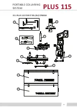
Страница 41: ...PORTABLE COLLARING SYSTEM 41 PLUS 115 15 1 PLUS 115 FOR STEEL EU 5700310 11 8 9 2 3 4 5 6 7 10 1...

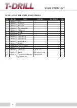
Страница 42: ...hole cutter 1 5 5700293 Drilling unit 1 6 5700301 Spindle 1 7 6700300 Pointer 1 8 5700304 Transport box 1 9 5700303 Transport box 1 10 5290206 Locking Lever 2 11 5700317 Tool set 1 12 5700118 Trimmin...

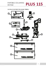
Страница 43: ...PORTABLE COLLARING SYSTEM 43 PLUS 115 15 2 PLUS 115 FOR STEEL USA 5700311 11 8 9 2 3 4 5 6 7 10 1...

Страница 44: ...Groove ball bearing 20 47x14 6204 2RS 2 13 9032408 Nilos ring 140 175 61828 JV 2 14 9018707 Parallel key 3x3x14 C45K PKR SMS2306 1 15 9024119 Roller chain 1 2 08 B 1 Wipperman 462 DIN 8187 1 16 90241...

Страница 45: ...PORTABLE COLLARING SYSTEM 45 PLUS 115 15 3 GEAR 5700307 8 10 20 11 13 17 12 9 7 6 18 23 21 14 4 1 2 22 Ruuvilukite Konekilpi liimataan Sikabond 500 Ruuvilukite 15 16 5 19 3 Ruuvilukite Ruuvilukite...

Страница 46: ...ty 1 4700062 Leadscrew 1 2 3700063 Cover 1 3 4700064 Bushing 1 4 4700065 Nut 1 5 4700066 Limiter nut 1 6 9014079 Socket head cap screw M6x8 8 8 DIN 7984 4 7 9016004 Set screw M6x6 12 9 DIN 913 1 8 902...

Страница 47: ...PORTABLE COLLARING SYSTEM 47 PLUS 115 1 2 3 5 8 7 4 6 9 15 4 LEAD SCREW 5700309...

Страница 48: ...plate 1 2 8003707 Index knob 22120_0376 1 3 9014020 Socket head cap screw M5x16 8 8 DIN 912 2 4 6700292 Clamp holder bar 2 5 9014316 Socket head cap screw M8x20 DIN 7991 4 6 4280104 Fastening pin 4 7...

Страница 49: ...PORTABLE COLLARING SYSTEM 49 PLUS 115 15 5 BASE PLATE 5700291 1 4 2 6 7 3 5...

Страница 50: ...lutch 40 80x22 CSK 40 PP 1 15 9018724 Parallel key 10x8x22 PKT 1 16 9014311 Socket head cap screw M5x10 DIN 7991 8 17 6700283 Adjusting bar A 1 18 6700284 Adjusting bar B 1 19 9014036 Socket head cap...

Страница 51: ...Type Std Manuf Qty 33 9016101 Set screw M4x5 12 9 DIN 914 1 34 9128016 Fixing lever M6x20 K1000 106 020 02 2 35 4700052 Locking pin 4 36 9013014 Self locking nut M12 DIN 985 4 37 9114070 Socket head c...

Страница 52: ...SPARE PARTS LIST 52 15 6 PILOT HOLE CUTTER 5700288 A A 16 13 17 4 5 8 10 10 26 21 7 9 34 3 1 2 29 30 6 32 33 37 38 A A 11 20 31 28 5 14 12 19 23 35 36...

Страница 53: ...PORTABLE COLLARING SYSTEM 53 PLUS 115 15 6 1 PILOT HOLE DRILL BITS Part No Name Size standard manufacturer 6310552 Drill 11 3 TiAlN For 21 3 head...

Страница 54: ...Blade L 19 3 11 4120155 Blade fastener 6 12 4700145 Measuring scale mm 1 13 9028088 Handle M6 Py riv Elesa 1 301 28 X M6 Elesa 1 14 9014029 Socket head cap screw M6x16 8 8 DIN 912 7 15 9014019 Socket...

Страница 55: ...PORTABLE COLLARING SYSTEM 55 PLUS 115 15 7 TRIMMING DEVICE 5700118 A 3 14 9 17 17 1 7 15 10 16 2 6 5 4 12 13 19 18 8 14 11...

Страница 56: ...330765 Lever 1 8 8003595 Knob 1 9 6080257 Pin M8 10x50mm 1 10 8000988 Slide bearing 8 14 18 3 MFM 0814 06 Igus 6 11 9012005 Washer 8 4 DIN 125 6 12 6330771 Hinge pin 2 13 9013035 Self locking nut M8 Z...

Страница 57: ...PORTABLE COLLARING SYSTEM 57 PLUS 115 15 8 DRILLING UNIT 5700293 A 3 1 7 6 15 16 17 2 19 4 5 13 12 11 10 14 9 8...

Страница 58: ...ST 58 15 9 SPINDLE 5700301 Pos Part No Name Size Type Std Manuf Qty 1 6310530 Spindle shaft 1 2 6700248 Sliding shaft 1 3 9019007 Retaining ring 25x1 2 DIN 471 Bl1 1 4 9016004 Set screw M6x6 12 9 DIN...

Страница 59: ...BLE COLLARING SYSTEM 59 PLUS 115 15 10 TRANSPORT BOX 5700303 Pos Part No Name Size Type Std Manuf Qty 1 5330774 Metal case 1 2 6700298 Moulded insert 1 3 6700302 Sticker Harmaa T DRILL PLUS 115 SS 1 1...

Страница 60: ...Part No Name Size Type Std Manuf Qty 1 5330774 Metal case 1 2 6700302 Sticker Harmaa T DRILL PLUS 115 SS 1 3 6700297 Moulded insert 1 4 6330895 Metal case 1 5 6700299 Moulded insert 1 15 11 TRANSPORT...

Страница 61: ...PLUS 115 15 12 LOCKING LEVER 5290206 A Pos Part No Name Size Type Std Manuf Qty 1 3290200 Lock body 1 2 4290203 Pusher 1 3 4290201 Pivot pin 1 4 4290202 Handle 1 5 4290204 Shaft 1 6 9019002 Retaining...

Страница 62: ...Pos Part No Name Size Type Std Manuf Qty 1 8004534 Ratchet 1 2 8004535 Socket 19mm 1 3 9051010 Allen key SW 14 DIN 911 1 4 9051014 Hexagon socket screw driver SW 4 L 150 1 5 9051017 Hexagon socket sc...

Страница 63: ...606 1700 004 Bernstein 1 2 9047245 Cable gland MS M 20x1 5 EN 50262 Skintop 2 3 9048341 Power cord 3x1 5 mm2x3000 VSBA3x1 5 280 3M SSTL 2440221 1 Pos Part No Name Size Type Std Manuf Qty 1 8004542 Foo...

Страница 64: ...ive drum 1 5 3700071 Bottom cover 1 6 3700072 Disk 1 7 4700073 Screw 2 8 4700074 Releasing screw 1 9 4700090 Key 4 10 9018049 Parallel pin 4m6x16 DIN 6325 1 11 9018080 Parallel pin 12m6x60 DIN 6325 1...

Страница 65: ...PORTABLE COLLARING SYSTEM 65 PLUS 115 3 9 13 2 8 2 1 14 4 6 7 10 11 12 5 15 16 COLLARING HEAD 2 2 5700148 C SST...

Страница 66: ...rive drum 1 5 3700071 Bottom cover 1 6 3700072 Disk 1 7 4700073 Screw 2 8 4700074 Releasing screw 1 9 4700090 Key 4 10 9018049 Parallel pin 4m6x16 DIN 6325 1 11 9018080 Parallel pin 12m6x60 DIN 6325 1...

Страница 67: ...PORTABLE COLLARING SYSTEM 67 PLUS 115 15 3 9 13 2 1 8 14 4 5 12 10 11 7 6 15 17 COLLARING HEAD 3 4 5700150 D SST...

Страница 68: ...0195 Ring Clamps NS 3 4290196 Ring Clamps NS 4 4290199 Ring Clamps NS 6 4290240 Ring Clamps NS 8 4290170 Ring Clamps 73 0 4290173 Ring Clamps 88 9 4290176 Ring Clamps 114 3 4290178 Ring Clamps 141 3 4...

Страница 69: ...type Qty 1 5330158 5330160 Power Unit Power Unit 120 V USA 230 V Europe 1 2 5330154 T 65 Tee Forming Unit 1 3 6330680 Adapter PUR 1 4 3330032 Tube Support 1 5 9114027 Socket head cap screw 2 6 6330674...

Страница 70: ...300056 Chuck ring 1 13 4300055 Chuck spring 1 14 4540069 Shaft 1 15 4300054 Chuck pin 2 16 3540045 Selector gear 1 17 9026146 Pressure spring 0 4 2 0x10 6 SS2387 Lesj fors Springs 2 18 9018089 Paralle...

Страница 71: ...PORTABLE COLLARING SYSTEM 71 PLUS 115 15 21 THE T 65 TEE FORMING UNIT 18 6 17 9 14 5 16 4 1 7 3 15 2 21 18 23 20 19 8 10 17 9 11 23 12 13 24 7 15...

Страница 72: ...le the technical file Juha Murtom ki Ampujantie 32 FIN 66400 LAIHIA FINLAND Confirms that the manually operated accessory T DRILL PLUS115 type code 7005 together with the T DRILL T 65 pipe collaring m...

Страница 73: ...dentification 2 1 Classification of the substance or mixture Classification according to Regulation EC No 1272 2008 CLP The mixture is classified as hazardous according to regulation EC No 1272 2008 C...

Страница 74: ...es of doubt or when symptoms persist seek medical advice 4 3 Indication of any immediate medical attention and special treatment needed First Aid decontamination treatment of symptoms SECTION 5 Firefi...

Страница 75: ...t any leaks 7 3 Specific end use s Observe technical data sheet SECTION 8 Exposure controls personal protection 8 1 Control parameters Occupational exposure limit values not applicable 8 2 Exposure co...

Страница 76: ...ction 7 10 3 Possibility of hazardous reactions Keep away from strong acids strong bases and strong oxidizing agents to avoid exothermic reactions 10 4 Conditions to avoid Stable when applying the rec...

Страница 77: ...mixture do not meet the PBT vPvB criteria according to REACH annex XIII 12 6 Other adverse effects No information available SECTION 13 Disposal considerations 13 1 Waste treatment methods Appropriate...

Страница 78: ...ive 92 85 EEC for expectant or nursing mothers Observe restrictions to employment for juvenils according to the juvenile work protection guideline 94 33 EC Substance product listed in the following in...

Страница 79: ...anisation for Economic Cooperation and Development PBT persistent bioaccumulative toxic PNEC Predicted No Effect Concentration REACH Registration Evaluation Authorisation and Restriction of Chemicals...

Страница 80: ...tomatic tube cutting machine for chipless tube cutting from coil and straight lengths Automatic cut length setting tube diameters 4 76 22 mm TCC 28 Transportable manually operated cutting ma chine wit...

Отзывы: