26
i.2.7
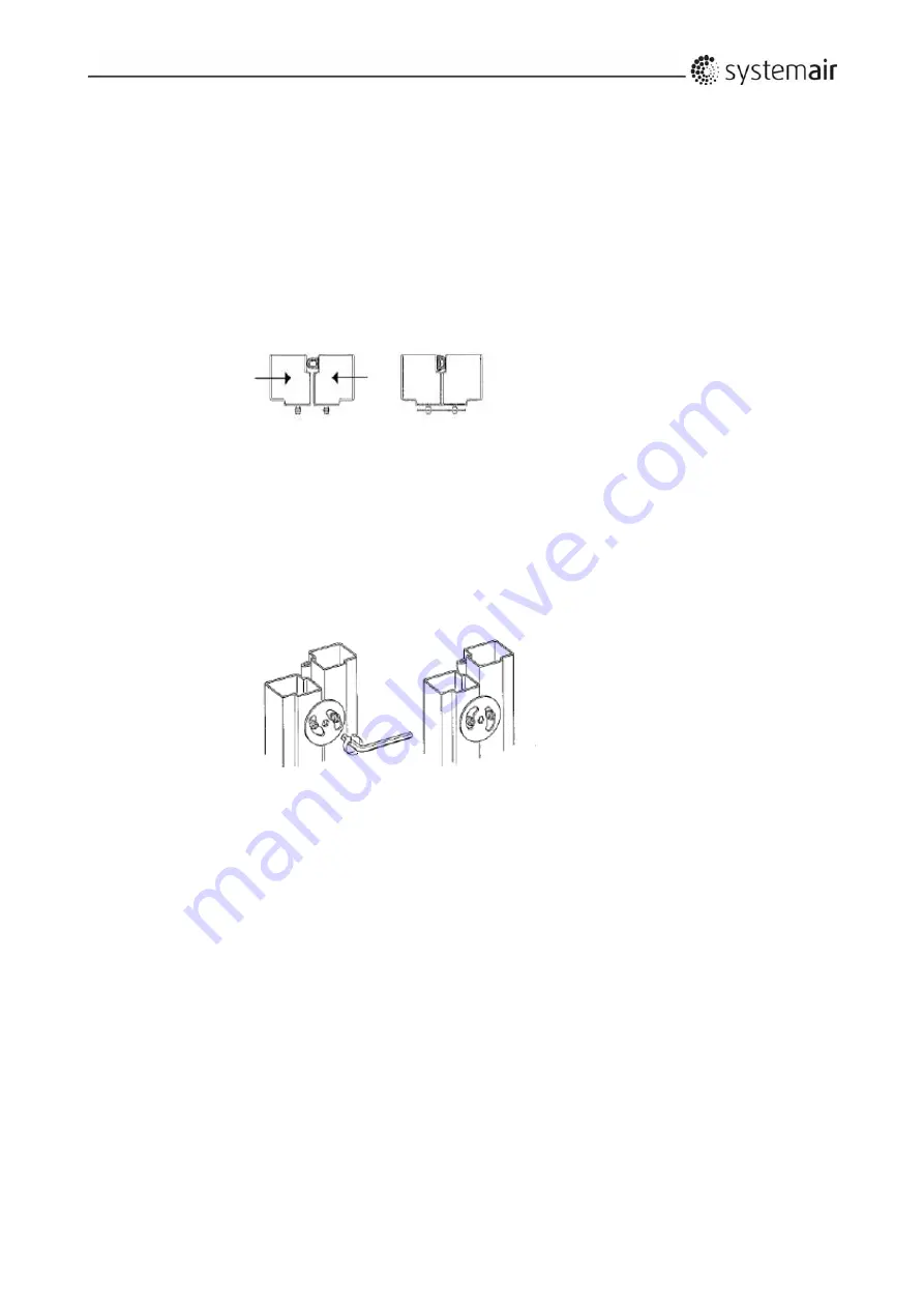
Joining
the
AHU
sections
The
sections
must
be
placed
on
the
base
frame
and
if
the
unit
is
delivered
with
100
mm
legs,
the
sections
must
be
positioned
directly
opposite
each
other.
1.
Ensure
that
the
internal
factory
‐
fitted
rubber
sealing
is
undamaged
2.
The
sections
are
then
to
be
positioned
directly
opposite
each
other.
If
the
sections
are
built
with
legs,
the
adjustable
feet
can
be
used
to
get
the
sections
parallel
and
at
the
same
height.
3.
Press
the
sections
hard
together
so
that
the
rubber
profiles
are
so
flat
that
the
iron
frames
of
the
two
sections
are
joined.
Straps
with
tensioner
as
shown
below
are
suitable
for
pressing
the
sections
hard
together.
4.
The
sections
are
then
to
be
locked
permanently
together
with
the
black
plastic
‐
coated
Systemair
Disc
‐
Locks.
The
Disc
‐
Locks
are
delivered
in
a
carton
box
placed
inside
the
unit.
Place
each
Disc
‐
Lock
over
the
2
factory
fitted
locking
pins.
The
discs
and
locking
pins
are
not
reliable
for
pulling
the
sections
together.
They
are
only
sufficient
for
keeping
the
sections
well
together,
so
just
turn
each
disc
gently
with
the
supplied
Allen
key.
Use
a
sequence
where
each
disc
is
tightened
with
only
one
click
at
a
time.
If
the
unit
is
placed
too
close
to
a
wall
with
no
space
left
for
the
mounting
of
Systemair
Disc
‐
Locks,
brackets
must
be
placed
inside
the
unit
to
keep
the
sections
permanently
together
(brackets
for
this
purpose
are
not
delivered
by
Systemair)
i.2.8
Fitting
the
ductwork
Flexible
duct
connections
between
AHU
and
ductwork
must
always
be
installed.
Be
sure
that
flexible
duct
connections
are
almost
fully
stretched.
(Flexible
connections
are
ordered
as
accessories
and
they
are
placed
inside
the
unit).
At
the
fan
outlet
on
a
centrifugal
fan,
the
duct
size
should
be
as
close
to
the
outlet
size
as
possible.
Avoid
blockage
and
turbulence
at
the
fan
outlet.
i.2.9
Risk
of
stack
effect
by
vertical
ducts
and
wind
pressure
on
louvers
On
special
occasions
stack
effect
–
also
called
chimney
effect
–
in
the
ducts
create
airflows
that
drives
the
impellers
by
turned
off
motors.
A
rotating
impeller
is
a
potential
hazard
during
cleaning
and
maintenance
of
the
unit.
Eliminate
this
airflow
by
dampers
with
spring
return
motors
for
automatic
closing
of
the
dampers
‐
even
by
power
failure.
Important!
The
Systemair
air
handling
units
can
be
ordered
and
delivered
without
dampers,
and
the
installer/user
must
check
that
duct
systems
with
the
described
risk
of
stack
effect
(chimney
effect)
will
be
provided
with
dampers
and
spring
return
motors.
Содержание Danvent DV-10
Страница 16: ...15 DVE Plug fan DVD Silencer DVX Humidifier...
Страница 57: ...56...
Страница 58: ...57 Annex for the User Manual Air Handling Units Danvent DV Without control system Version 1 01 13...
Страница 84: ...8 8...
Страница 88: ...9 4 9 1 3 Information about connection of cables to terminals on the control board...
Страница 91: ...9 7...
Страница 92: ...9 8 A1 Size Quantity Length mm DV 60 4 1014 DV 80 4 1164 DV 100 4 1314 DV 120 4 1464 DV 150 4 1614 A1...
Страница 94: ...9 10 9 3 Assemble divided rotor from Hoval Enventus for DV 60 DV 80 and DV 100 9 3 1 Tools and aids 0 100Nm 3 3...
Страница 103: ...9 19...
Страница 111: ...12 3...
Страница 115: ...12 7 Frequency converter is always necessary for the control of each PM motor...
Страница 119: ...13 1 Annex 13 Commissioning See separate cover with annexes 1 2 3 and 13...


