background image

page


3

January 2020 - Rev. 1.2

Order Cod. 1902503003

1. General characteristics

The 

Quad Microstep drive

 unit is designed to control 

and  monitor  up  to  four  two-phase  stepper  motors, 

operating in bipolar chopper mode.
The drive is equipped with a high performance trajectory 

generator  and  with  a  digital  control  system  of  the 

current  supplied  to  ensure  smooth  and  silent  motor 

movement.
Microstepping  generation  is  achieved  digitally  and 

is  configurable  remotely,  as  well  as  all  the  operating 

parameters that can be varied via the field bus in use 

(the  use  of  configuration  jumpers  or  the  like  is  not 

required).

The drive is always equipped with a 

master

  board 

containing the global control electronics and the power 

section for two motors; an 

expansion


board is connected 

to the master board and allows to control two additional 

motors. The expansion board also provides 16 digital 

24V isolated outputs and 16 digital inputs.
A  front  display  and  keyboard  allow  to  rapidly  view 

the  main  configuration  parameters  and  status  of  the 

drive.

The general characteristics of the system are:

• 

Open type

• 

Limited dimensions: 375×190×80

• 

High performance thanks to the use of Mosfet in 

the power stage

• 

Silent due to an operating frequency equal to 

25KHz

• 

Complete work parameter setting from remote

• 

Front display and keyboard to verify some 

operating parameters

• 

Management of step fractionation up to 1/256 

steps per step (for example, with motors operating 

at 200 steps/revolution one can achieve positioning 

resolutions up to 51200 microsteps/revolution). 

The use of microstepping also allows to obtain less 

motor heating and increased silentness in rotation. 

The maximum generated frequency is in any case 

equal to 622500 microstep/s

• 

Optimal integration between the control stage, 

power stage and inputs-outputs: in fact the 

Microstep unit features a PMD indexer integrated 

on-board, capable of handling 4 independent axes 

with trapezoidal, velocity and S-curve profiles

• 

16 digital 24V isolated inputs and 16 outputs 

• 

Control of stepper motors at 25V - 160V

max

 and 1A 

- 13A

• 

Guards:

•  Protection against short-circuit between the motor 

phases

•  Protection  against  incorrect  wiring  (phases  not 

connected)

•  Protection against overtemperature

•  Protection against short-circuit between a phase 

and the drive power supply

• 

Fault management and report

• 

Remote reading of the power stage temperature

• 

Remote reading of the motor supply voltage

• 

Report of failure to reach the current set-point 

while in motion.

• 

UL certified

2. Technical specifications

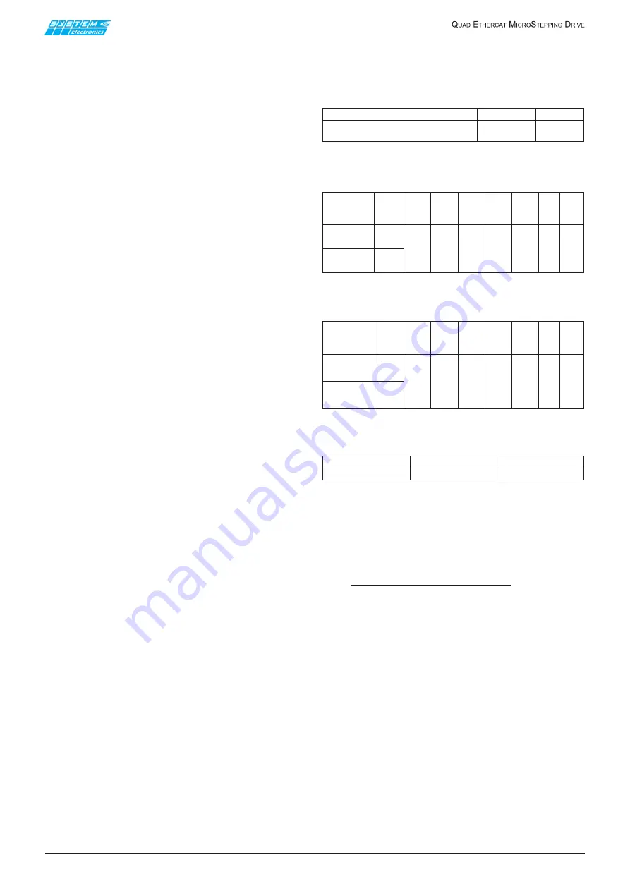
2.1 Electrical ratings

1. Power Input

Terminal

Voltage

Current

+V34-GND (XT2, pin B1,B2,B3,B4)

+V12-GND (XT1, pin B10,B11,B12,B13)

160Vdc

7A

Table 2.1.1

2. Power Output

Table 2.1.2

3. OPTIONAL Power Output


Table 2.1.3

4. Control Supply 24V Input

Table 2.1.4

Power supply separated and isolated from the control 

power supply and I/O

• 

Motor power supply min 25V max 180V. Separate 

motor power supply for pairs of motors 1-2 and 3-

4: 

while maintaining the same mass

, it is possible 

to power motors with different voltages or partly 

disable them

• 

The power supply of the pair of motors 1-2 shares 

the same GND of the pair of motors 3-4. The GND 

can be connected to the PE depending on the 

application

• 

Power section operating temperature max 90°C

• 

Minimum operating temperature 0°C

• 

Reading via field bus of the power stage dissipators 

temperature of each pair of motors


Temperature readings “1” and “2” refer to the pair 

of motors 1 - 2; temperature readings “3” and “4” 

to the pair of motors 3 - 4 (motors 1 and 2 share 

the same dissipator, just as motors 3 and 4)

• 

Programmable setting of the dissipator 

overtemperature threshold (<90°C)

• 

Remote reading of the motor supply voltage

• 

Protection of every single motor with fuse on the 

removable front terminal board. Fuse installed: 

10A F 250V 

(See par. 2.6 for details)

Terminal

Output

Voltage

Current

(Arms)

per

terminal

Max

two

phases

output

current

Peak

Current

Freq.

Power

Duty

Cycle

AN1-A1-BN1-B1

XT1, pin B6,B7,

B8,B9

AN2-A2-BN2-B2

XT1, pin B2,B3,

B4,B5

Motor 1

Motor 2

Max

160Vac

7A

Max

13A

Max

155KHz

2.7hp

10A

RMS

0-100%

Terminal

Output

Voltage Current

Max

two

phases

output

current

Peak

Current

Freq.

Power

Duty

Cycle

AN3-A3-BN3-B3

(XT2, pin B9,

B10,B11,B12)

AN4-A4-BN4-B4

(XT2, pin B5,

B6,B7,B8)

Motor 3

Motor 4

Max

160Vac

7A

Max

13A

Max

155KHz

2.7hp

10A

RMS

0-100%

Terminal

XP10

Voltage

24 Vdc

Current

0.5A

Содержание 1902503003

Страница 1: ...specifications 3 3 Display and keyboard 6 4 Axes management Firmware update 10 5 Standard drive profile 12 6 Units of measure for the kinematic parameters 14 7 WEB interface 15 8 CANopen interface 15...

Страница 2: ...336 CEE and subsequent amendments SYSTEM CERAMICS SPA reserves the right to make changes of any kind to the technical specifications at any time without prior notice The information contained in this...

Страница 3: ...ction against short circuit between the motor phases Protection against incorrect wiring phases not connected Protection against overtemperature Protection against short circuit between a phase and th...

Страница 4: ...ON The Drive is equipped with Solid State Short Circuit Protection EXTERNAL RECOMMENDED PROTECTION FUSES R C Special purpose Fuses JFHR2 JFHR8 manufactured by COOPER BUSSMANN LLC E91958 model FWP 40B...

Страница 5: ...le for update management the firmware is called Monitor Firmware updatable for the management of the axes according to the protocol CiA DSP 402 2 8 I O section 16 digital inputs isolated from the powe...

Страница 6: ...ement firmware release Monitor firmware release Communication mode modifiable EtherCAT node address modifiable CAN network bit rate modifiable CAN network termination and slope resistors modifiable CA...

Страница 7: ...ive live parts Attention Parties actives internes haute tension dangereuses 3 1 5 Dissipator temperature display page T1 27C T2 28C T3 27C T4 24C Displays in degrees Celsius the internal temperature o...

Страница 8: ...ic one can force the address by changing it manually Default value 0 3 2 5 CAN communication Speed Display Setting CAN Open Bit rate 500 Kbps Displays the CAN communication speed and allows to modify...

Страница 9: ...o back to the main menu one is prompted whether to save the data permanently Save Parameters NO Using the arrows and one can choose between the following saving options NO The modified parameters are...

Страница 10: ...companied by relevant messages on the display This process can obviously be automated so that all drives present on a network are updated in parallel Make sure you have a power supply with the correct...

Страница 11: ...or the download OK message to appear and press the VALIDATE FIRMWARE button Figure 4 2 7 At the end wait for the validation OK message to appear and press the REBOOT button or switch the Quad on and o...

Страница 12: ...2800 and 0x2FFF Objects defined by System SpA for axis 2 Between 0x3000 and 0x37FF Objects defined by System SpA for axis 3 Between 0x3800 and 0x3FFF Objects defined by System SpA for axis 4 Between 0...

Страница 13: ...pecial Setting 1 rw Sub 1 pp Parms change on NewSetpoint 2 8 0x2010 Analog Data 3 ro Sub 1 Actual Current 0 1A USINT 8 0 ro Sub 2 Temperature 0 1 3 8 SINT 0 ro Sub 3 Voltage V USINT 8 0 ro 0x20FD Stat...

Страница 14: ...ondary DNS 32 UDINT ro 0x00000000 0 0 0 0 0x4005 EtherCAT Address ID 16 UINT 0 ro 0x4006 Comunication Mode 1 8 USINT 0 rw 0x4007 CANopen Parameters 4 ro Sub 1 Bit rate 2 8 USINT ro 2 Sub 2 Node Addres...

Страница 15: ...commended for controlling motors it is only envisaged as an internal tool for System Spa developers NOTE Do not connect the Ethernet cable during normal operation of the drive and replace the connecto...

Страница 16: ...the slots on the base The upper slots of the base are located in mobile elements held in place by springs The mounting base must be fixed first The unit is inserted by placing the upper teeth on the...

Страница 17: ...ch steady state conditions given by the formula V L dI dt where I is the maximum current applied typically the boost current starting from standstill One must maintain a safety margin to prevent excee...

Страница 18: ...ure 11 1 1 XP10 POWER 24Vdc Control board 24V power connector 1 24Vdc 2 REF 24 3 4 GND Max current 0 5A GND Connect to the Ethernet ETH1 RJ45 normally NOT used This connector features a dust proof cap...

Страница 19: ...the following fuse available from System SPA Code 70000650 FUSE RAP 10A 5X20 250VDC 50CF 100H HOLLYLAND E156471 Connect all PE terminals to the protective earth of the main circuit Description Label P...

Страница 20: ...e logic board 11 5 Front terminal board 1902503003 I O Connection Table 11 5 1 Num Description 40 REF I O 39 24 I O 38 REF I O 37 24 I O 36 REF I O 35 24 I O 34 REF I O 33 24 I O 32 OUT16 31 OUT15 30...

Страница 21: ...r LEDs Green LEDs I1 I16 on with active input high for inputs IN1 IN16 respectively Red LEDs O1 O16 on with active output high for outputs OUT1 OUT16 respectively 12 2 Connection cables for terminal d...

Отзывы: