


page
15
January 2020 - Rev. 1.2
Order Cod. 1902503003
For example, if one wants to obtain a speed of 50000
microstep/s
2
, one must calculate the following:
The parameters with one jerk dimensions (first derivative
of acceleration) must be intended as unsigned 32-bit
integers; these integers (actually fixed point numbers
in format 0:32) are obtained by multiplying by 2
32
) the
number of microsteps/cycle
3
.
For example, if one wants to obtain a jerk of 500
microstep/s
3
, one must calculate the following:
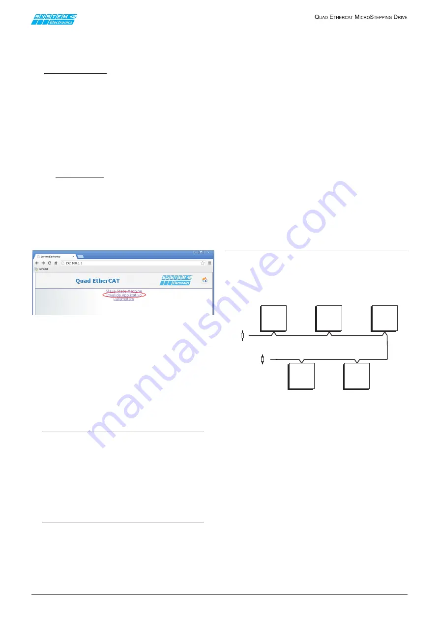
7. WEB interface
The axes management firmware contains a web server
that allows to interface the drive with any browser.
Figure 7.1
From the Home Page one can access three different
pages:
1.
“Firmware invalidation” and “drive reset” page.
This page is very useful if one wants to update the
axes management firmware via the browser.
2.
Management page (partial) of the drive automaton
state.
3.
Web controlled movements management page.
NOTE:
The use of the last two pages listed requires the
drive being set (via the front keypad) in CANopen
communication mode (actually, CANopen/
Ethernet) and is strongly unadvised. Ethernet/
HTTP communication, in fact, is not real-time
and is not recommended for controlling motors;
it is only envisaged as an internal tool for System
Spa developers.
NOTE:
Do not connect the Ethernet cable during normal
operation of the drive and replace the connector
protection cap at the end of the operation.
8. CANopen interface
The drive is equipped with a CAN communication port
and is designed to operate as a CANopen node and it
is actually allowed to set (via the front keypad) the
CANopen communication mode, as well as the CANopen
node address, the bit rate (between 10 kbps and 1
Mbps), the insertion of the termination resistor and
the slope control (in the event the transmission rate is
particularly high, i.e. above 500 kbps).
At present, however, there is NO CANopen object
implemented that allows the use of the drive for axes
management.
Default configuration:
•
Transmission speed 500Kbit
•
Termination NOT inserted
•
Slope inserted
For settings refer to paragraphs 3.2.5, 3.2.6 and
3.2.7.
Connection to the CAN network
The physical medium used for the connection is a
shielded two-wire cable. The arrangement of the nodes
must be such that the termination resistors are placed
at the two ends of the network; it is also advisable to
make the connections avoiding T connections.
Figure 8.1
120 ohm
120 ohm
Acceleration = 50000 microstep/s
²
50000 * 65536
3906.25
²
= 214 (format 16:16)
Jerk = 500 microstep/s
²
500 * 2
³²
3906.25
³
= 36 (format 0:32)


