background image

Users Manual – svs4021, svs2020,svs2050, svs2051, svs1020, svs1050, svs285, svs340, svs625

p. 55

Last Update 20.07.2009

16 Appendix B – Basic timing for different operation

modes

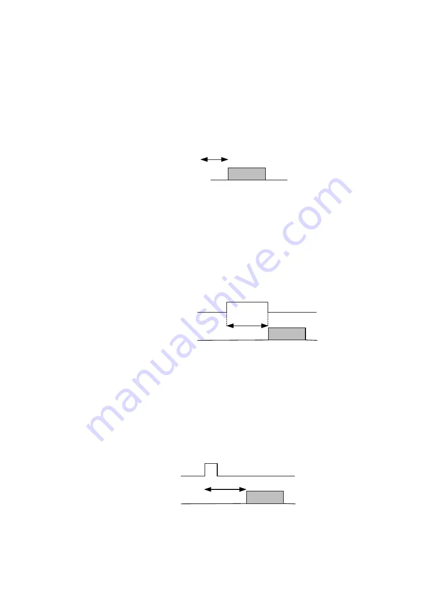
16.1 Free Running

A frame is readout automatically. There is no need to trigger the camera in
order to get data. The enclosed software allows the user to set exposure time in

µSec. The time set stays resident after power off if the configuration is saved to
camera if stored before.

16.2 External Trigger and Pulsewidth of Trigger

In this mode the camera is waiting for an external trigger which starts
integration and read out. Exposure time can be varied using the length of the

Trigger pulse (I.E. between the high going edge and the low going edge). The
time settings in the control software are not activated. This mode is useful in

applications where the light level of the sceen changes during operation and the

framegrabber can provide such a signal. Change of exposure time is possible
from one frame to the next.

16.3 External and Software trigger and internal exposure time

setting

The frame rate is determined by the number of Trigger pulses per time unit.

With each positive transition (going high) the camera will readout a frame.

Exposuretime is set in the same way as in the free running mode. Exposure
time can be changed online during operation. The time set stays resident after

power off, if the configuration is saved to the camera.

Data

Exposure

time

Trigger

Data

Exposure

time

Data

Exposure

time

Trigger

Содержание svs1020

Страница 1: ...USERS MANUAL SVcam CF series svs340 424 414 204 1020 1050 285 2050 2051 2020 274 4021 and 625 Gigabit Ethernet GigE Line Digital Progressive Area Scan Camera Version 1 4 9_4 Last Update 20 07 2009 ...

Страница 2: ...Users Manual svs4021 svs2020 svs2050 svs2051 svs1020 svs1050 svs285 svs340 svs625 p 2 Last Update 20 07 2009 ...

Страница 3: ...20 svs1020 svs285 svs204 svs340 svs424 svs625 p 3 Last Update 20 07 2009 Contact SVS VISTEK GmbH Mühlbachstraße 20 82229 Seefeld Obb Germany Tel 49 0 8152 99 85 0 www svs vistek com Service contact E Mail service svs vistek com ...

Страница 4: ...onsiderations 17 3 2 5 Connecting multiple cameras to a PC 18 3 2 6 Multicast 18 4 WINDOWS X64 SUPPORT 20 4 1 1 Displaying live images 20 5 CAMERA SETTINGS DIALOG 23 5 1 1 Camera 23 5 1 2 Network 24 5 1 3 Acquisition 24 5 2 IMAGE 25 5 3 GAIN 26 5 4 OFFSET 26 5 5 AUTO TAP BALANCE 26 5 6 AUTOGAIN AUTOEXPOSURE 27 5 7 ADJUSTING AN AOI AREA OF INTEREST 28 5 8 STROBE 28 5 9 PERSISTENCE 28 6 SAVING IMAGE...

Страница 5: ... 1 OVERVIEW 57 17 2 PREREQUISITES 57 17 3 SVGIGE SDK COMPONENTS 57 17 4 DEVELOPMENT ENVIRONMENTS 58 17 5 WINDOWS X64 SUPPORT 58 17 6 DOCUMENTATION 59 17 7 SYSTEM ARCHITECTURE 59 17 8 FUNCTION GROUPS 60 17 9 DETAILED FUNCTION LISTING 61 17 10 BEST PROGRAMMING PRACTICES 67 17 10 1 Connecting to the camera container 67 17 10 2 Connecting to a camera 67 17 10 3 Identifying a camera 68 17 10 4 Opening ...

Страница 6: ...Users Manual svs4021 svs2020 svs2050 svs2051 svs1020 svs1050 svs285 svs340 svs625 p 6 Last Update 20 07 2009 ...

Страница 7: ...monochrome and color version svs1050 1 2 CCD 1024 x 1024 Pixel 12 Bit gray level resolution approx 60 frames sec monochrome and color version svs424 1 3 CCD 640 x480 Pixel 10 Bit gray level resolution approx 116 frames sec monochrome and color version svs204 1 3 CCD 1024 x 768 Pixel 10 Bit gray level resolution approx 50 frames sec monochrome and color version svs285 2 3 CCD 1360 x 1024 Pixel 10 1...

Страница 8: ...40 svs625 p 8 Last Update 20 07 2009 For standard applications only 8 Bit are transmitted due to data load For more information on the color versions please see chapter 12 11 If you need modifications we will be glad to offer you a custom camera suitable to your application ...

Страница 9: ...ect laser beam as this could damage the sensor See Safety Instructions at Warranty will be void if not followed 2 1 Unpacking Camera Power supply if ordered option Mating connector first cameras delivered User Manual Disk with SDK including High Performance Driver API and GUI SVCapture for GigE camera program Also a Firmware update tool XML File according to GenIcam standard released by AIA commit...

Страница 10: ...It is recommended to use a PC with a Pentium P4 processor at 2 4 GHz or higher The camera is working also on lower frequencies but it might not deliver the full frame rate in those cases If the camera is connected to the PC directly without using a network switch a fixed IP Address and Subnet Mask has to be configured in the PC s TCP IP settings See Start Settings Network connections LAN connectio...

Страница 11: ...erface which connects via Ethernet standard cable CAT 5E quality is required The default factory setting is Free Running Fixed Frequency using the internal logic for exposure control You can also trigger the camera by hardware and by PC software trigger The color version will come on request with free software algorithm which will allow processing of the color image inside the PC or the camera Thi...

Страница 12: ...hen use this mode You still can use the SVCapture GUI for setting exposure time see Exposure time field below However you need to use the Exsync signal in order to trigger the camera see Trigger buttons below External triggered via Software trigger with internal exposure control If you want to trigger the camera with a software trigger and use the SVCapture exposure time control of camera logic th...

Страница 13: ...w You will observe a loss of frames if you do not use the driver If you have installed the camera and connected the power you can install the driver and the GUI to do the first test Copy the SVCapture exe to your disk drive double click on the SVCapture icon and a window will open The software SVCapture displays images sent from SVS GigE Cameras via Gigabit Ethernet to your PC with Windows XP and ...

Страница 14: ...used by inappropriate network settings In this case the camera s network settings have to be adjusted first before getting it into an operational mode Adjust settings accordingly Settings Network connections LAN connection Properties TCP IP In a network with a DHCP server the camera will obtain its IP address automatically and the settings shown in the screenshot above will be on Obtain an IP addr...

Страница 15: ...nk Address is recommended This involves a network mask 255 255 0 0 as well as a fixed first part 169 254 xxx xxx of the network address range A GigE camera will fall back to LLA soon after recognizing that no DHCP server is available and that no fixed network address was assigned to the camera In case a camera can not be reached by the SVCapture application a dialog will appear that allows for adj...

Страница 16: ...d name can be used for this purpose Usually the DHCP method is convenient for involving a camera in to an already existing network of computers which all obtain their IP addresses from a DHCP server The camera will well behave in this environment when adjusting it also to the DHCP mode In some cases it may be that a camera will be connected for performance reasons directly to a dedicated network c...

Страница 17: ...work ports Other cards have to be checked whether they contain an adjustment which allows for switching jumbo frames on NOTE For Intel Pro 1000 cards the settings should be adjusted as follows Flow control Generate Interrupt throttling rate Minimal Jumbo frames adjust to maximal value All SVCam GigE cameras support flow control and jumbo frames upto 16112 bytes 3 2 4 Performance considerations Eac...

Страница 18: ...will not allow for operating the camera at highest framerate but only on lower framerates 3 2 5 Connecting multiple cameras to a PC Multiple GigE cameras can be connected to a PC either using a switch or using dual or quad port network interface connectors NIC The following image shows the basic connection schemes which may also be combined HINT Highest performance requires connecting each camera ...

Страница 19: ... the Device Discovery dialog before opening a camera It is important to enter a suitable maximal packet size This packet size is determined as the minimum packet size from all intended listeners When for example all applications but one have jumbo frames adjusted to 16112 bytes and the one application has jumbo frames adjusted to 9000 bytes then the minimum 9000 has to be entered in the above show...

Страница 20: ...which are provided by the driver Nevertheless SVCapture can use Winsock for both communicating to a camera as well as streaming image data from the camera to the application NOTE Though a Winsock connection to a camera can be established properly also on x64 platforms there exist the same limitation for image streams regarding transport reliability also on that platform Usually a certain amount of...

Страница 21: ... will display all available cameras in the network after a short time of discovery Cameras that become available or unavailable in the network will cause the list to expand and shrink dynamically A green Discover lamp signals that the network is scanned for those changes usually once per second The screenshot below shows one camera connected ...

Страница 22: ...icking on the camera entry a live image will be displayed The caption of the program window shows the program name and the current version whereas the caption of the camera view shows the camera name and camera firmware version along with the MAC address that the camera has been set during manufacturing and prior to shipping as default values ...

Страница 23: ... Camera menu brings up a settings dialog that allows for accessing the various camera settings While adjusting settings in the dialog the new values are transferred to the camera continuously and the live image will respond to all changes immediately In particular the following information and settings are available 5 1 1 Camera In the camera panel the following information is queried from the cam...

Страница 24: ...tware Interface of the PC It is controlled by the internal FPGA No further external signals The enclosed program allows the user to set the values from e g about 1 100 000 sec to 1 second Exposure time can be changed online during operation The framerate can be adjusted as well External trigger and using Pulse width of Trigger external exposure In this mode the camera is waiting for an external tr...

Страница 25: ...etwork interface In case of multiple cameras or other devices working on the same physical network it might be desirable to send the packets of a camera s streaming channel with a certain inter packet delay in order to allow multiple cameras or devices to share a given network bandwidth NOTE The inter packet delay should be below the value which would decrease the frame rate 5 2 Image The image pa...

Страница 26: ...r good image quality do not increase gain more than 6 dB higher Gain is possible but not specified For F version of svs1020 1050 2020 2050 2150 and 4021 only Please note that the CCD is used with 2 outputs Therefore there are a right and a left image half If you use the slider both channels are amplified However depending on the amplifications there might be different values necessary in order to ...

Страница 27: ... used for evaluating tap balance Current tap balance will be displayed numerically in a range from 1 5 dB to 1 5 dB as well as graphically by a slider The slider can also be used for manually adjusting arbitrary gain factors The check box Gain balance has to be checked in order to enable the slider for manual adjustments Current balance settings can be saved into a file and restored later using th...

Страница 28: ... AOI by dragging and resizing a gray target area with a red border inside the imager limits represented by a rectangle with black borders Whenever the left mouse button is released after dragging resizing the target area the camera will be adjusted to the new settings Alternatively the target area can be defined numerically by entering values into the edit fields for Size Offset and subsequently c...

Страница 29: ...to disk The live image can be saved to disk with the Save as item in the Image menu After selecting a path and specifying a file name a picture in one of the formats JPEG PNG Portable Network Graphics BMP or PIX raw pixel data will be saved to disk Saving of 16 bit images is supported by the PNG and PIX raw pixel data formats ...

Страница 30: ...rbitrarily assigned to actual data lines The following outputs are available OUT0 OUT1 OUT2 OUT3 OUT_TXD The following input lines are available UART_IN Trigger When clicking on Apply after making all adjustments then the new assignments take effect One has to click on Save to EEPROM in order to make them persistent In case of any problems the Factory defaults can be restored by clicking on that b...

Страница 31: ... to the GigE Vision standard a GigE camera provides for an XML file that defines the camera s capabilities Though the XML file will usually be processed by software the SVCapture application allows for displaying a camera s XML file on screen and saving it to disk This functionality is available in the Camera menu when clicking on the Show XML file entry ...

Страница 32: ...ures The Feature list entry in the Camera menu allows for getting information which features a given camera provides for and which are not available 10 Other menu items File Enable filter driver Enable or disable a filter driver File Exit Leaving application Window Cascade Cascade camera views in main window Window Tile Assign each camera view a share of main window Window Delete Close camera view...

Страница 33: ...f an image to 12 5 Reducing the size of an image to 25 Reducing the size of an image to 50 Restoring the original 100 size of an image Magnifying resolution to 200 image fragment scrolled by left mouse click Magnifying resolution to 400 image fragment scrolled by left mouse click Magnifying resolution to 800 image fragment scrolled by left mouse click If Pixel values is selected the display switch...

Страница 34: ... to execute a firmware update Depending on the serial number a firmware update for the internal camera logic might be useful or necessary This can be essential in order to use the current available SVCapture or SDK Using unmatched hardware and software e g HW 1 2 with SW 1 4 will NOT work Numbering is consistent So 1 4 SW requires 1 4 firmware In doubt please contact your local distributor ...

Страница 35: ...details are available in the Kodak spec sheets available at www Kodak com Interline Transfer CCDs Spectral range 400 900 nm B W COLOR version RGB Bayer Mosaic Filter see 12 11 12 2 Gain balancing for versions svs1020 1050 2020 2050 2051 svs4021 and 625 only The output for the F L or other 2 tap version is as follows 2 taps are read out and the right half of the image is mirrored It is put together...

Страница 36: ... the camera Those settings determine the zero point for the user accessible gain and offset values usually called calibration values The factory settings for those values become available for change when clicking on the Calibrate button A warning will be issued as follows After confirming the warning dialog with OK a Sensor ADC panel becomes available and replaces the Luminance panel Clicking on L...

Страница 37: ...hanical issues 12 5 svs424 204 and svs285 only Camera size 50mm x 55mm x 80mm without connectors and lens Weight Approx 300 gram Front plate with M 42 x 1 threads and C Mount adapter for 4021 all others with C Mount Distance from Chip surface to frontplate 11 65mm Please note The C Mount adapter of svs4021 is intended for easy setup However it might cause dark edges due to a loss of light in the c...

Страница 38: ...1 Distance from chip surface to front plate of C Mount 17 5mm Mating connector MC 1 5 7 STF 3 81 Order 18 27 75 8 V0 made by Phoenix Contact Hood for connector KGG MC 1 5 7 Order 18 34 39 8 made by Phoenix Contact Male connector Type Phoenix Contact Pin 1 12V to 15 V DC Pin 2 GND Pin 3 Shield Pin 4 Trigger Pin 5 Trigger Pin 6 Strobe OUT Pin 7 Strobe OUT View on mounting side svs285 65 10 5 11 05 3...

Страница 39: ...5mm Mating connector MC 1 5 7 STF 3 81 Order 18 27 75 8 V0 made by Phoenix Contact Hood for connector KGG MC 1 5 7 Order 18 34 39 8 made by Phoenix Contact Male connector Type Phoenix Contact Pin 1 12V to 15 V DC Pin 2 GND Pin 3 Shield Pin 4 Trigger Pin 5 Trigger Pin 6 Strobe OUT Pin 7 Strobe OUT View on mounting side svs625 svs2020 svs4021 M 42 x 1 to C Mount adapter is a standard when svs4021 is...

Страница 40: ...tio 8 5 Bit Saturation Dark Noise RMS Fixed Pattern Noise 2 counts in 10 Bit Photo Response Non uniformity PRNU 10 Spectral Response 380 950 nm Monochrome Exposure Time 3 µsec 2 sec svs340 CCD KAI 340 1 1 3 Interline 640 x 480 Pixel Pixel Size 7 4 x 7 4 µm Readout Frequency 2 x 50 MHz Frame Rate max 264 Frame Rate 2 x 2 Binning 495 fps Offset ca 2 counts in 8 Bit Gain 0 to 6 db S N Ratio 8 5 Bit S...

Страница 41: ...e RMS Fixed Pattern Noise 2 counts in 10 Bit Photo Response Non uniformity PRNU 10 Spectral Response 380 950 nm Monochrome Exposure Time 17 µsec 2 sec svs1020 U version CCD KAI 1020 2 3 Interline 1000 x 1000 Pixel Pixel Size 7 4 x 7 4 µm Readout Frequency 2 x 50 MHz Frame Rate max 72 fps Frame Rate 2 x 2 Binning 119 6 fps Offset ca 2 counts in 8 Bit Gain 0 to 6 db S N Ratio 8 Bit Saturation Dark N...

Страница 42: ...sion 8 Bit Fixed Pattern Noise 8 count in 12 Bit Photo Response Non uniformity PRNU 10 Spectral Response 380 950 nm Monochrome Exposure Time 6 µsec 2 sec svs285 F CCD ICX 285 2 3 Interline 1360 x 1024 Pixel Pixel Size 7 4 x 7 4 µm Readout Frequency 1 x 50 MHz Frame Rate max 26 fps Frame Rate 2 x 2 Binning 45 fps Offset ca 10 counts in 10 Bit Gain 0 to 6 db S N Ratio 8 5 Bit Saturation Dark Noise R...

Страница 43: ...xed Pattern Noise 2 counts Photo Response Non uniformity PRNU 10 Spectral Response 380 950 nm Monochrome Exposure Time 31 µsec 2 sec svs2020 S version CCD KAI 2020 1 1 4 Interline 1600 x 1200 Pixel Pixel Size 7 4 x 7 4 µm Readout Frequency 1 x 40 MHz 1 tap Frame Rate max 18 5 fps Frame Rate 2 x 2 Binning 34 Offset ca 40 counts in 12 bit Gain 0 to 6 db S N Ratio 9 Bit Saturation Dark Noise RMS Colo...

Страница 44: ...e RMS Color version 8 Bit Fixed Pattern Noise 8 counts in 12 bit Photo Response Non uniformity PRNU 10 Spectral Response 380 950 nm Exposure Time 19 µsec 2 sec Monochrome svs2050 L CCD KAI 2050 2 3 Interline 1600 x 1200 Pixel Pixel Size 5 5 x 5 5 µm Readout Frequency 2 x 40 MHz 2 taps Frame Rate max 31 fps Frame Rate 2 x 2 Binning 55 fps Offset ca 30 counts in 12 Bit Gain 0 to 6 db S N Ratio 9 Bit...

Страница 45: ...Fixed Pattern Noise 8 counts in 12 bit Photo Response Non uniformity PRNU 10 Spectral Response 380 950 nm Exposure Time mode 2 80µsec 1 6 sec Monochrome 4021 S version CCD KAI 4021 1 1 4 Interline 2048 x 2048 Pixel Pixel Size 7 4 x 7 4 µm Readout Frequency 1 x 40 MHz 1 tap Frame Rate max 8 fps Frame Rate 2 x 2 Binning 16 fps Offset ca 40 counts in 12 bit Gain 0 to 6 db S N Ratio 9 Bit Saturation D...

Страница 46: ...e RMS Color version 8 Bit Fixed Pattern Noise 8 counts in 12 bit Photo Response Non uniformity PRNU 10 Spectral Response 380 950 nm Monochrome Exposure Time mode 2 50 µsec 2 sec svs625 CCDICX 625 2 3 Interline 2448 x 2050 Pixel Pixel Size 3 45 x 3 45 µm Readout Frequency 2 x 50 MHz Frame Rate max 15 fps Frame Rate 2 x 2 Binning 25 fps Offset ca 2 counts in 8 Bit Gain 0 to 6 db S N Ratio 8 Bit Satu...

Страница 47: ... and can radiate radio frequency energy and if not installed and used in accordance with the instruction manual may cause harmful interference to radio communications Operation of this equipment in a residential area is likely to cause harmful interference in which case the user will be required to correct the interference at his own expense Camera complies with FCC Form 47 Rules It is necessary t...

Страница 48: ...9 12 9 Spectral response curves Monochrome Version All Color Version svs4021 svs2020 svs424 svs204 0 0 0 1 0 2 0 3 0 4 0 5 0 6 0 7 0 8 0 9 1 0 400 500 600 700 800 900 1000 Wavelength nm R elative resp onse W avelength nm R elative response 0 0 0 2 0 4 0 6 0 8 1 0 400 450 500 550 600 650 700 svs285 Monochrome ...

Страница 49: ...ixel in the blue line Because this camera is a single chip camera it is necessary to use an algorithm which interpolates those colors which are not known by the specific pixel E g the red pixel does not know its green and blue components This means that the performance of the image depends on the software used Please be aware that it is not possible to incorporate the algorithm into the camera so ...

Страница 50: ...uyer of the amount of said evaluation and handling charges at the time the return authorization is issued The Seller will inform the Buyer of related repair and or replacement costs and request authorization before incurring such costs Buyer shall identify all returned material with Sellers invoice number under which material has been received If more than one invoice applies material has to be cl...

Страница 51: ...iagnostics menu entry a dialog will open that allows for receiving camera diagnostics information The content of the Diagnostics window is low level register information Usually it is needed only for remote analysis purposes of problem situations The following items provide some hints how to solve problem situations where a connection between a PC and a camera can not be established successfully ...

Страница 52: ...nt network card Problem No communication is possible between the camera and the PC Solution Check if a firewall is active This can prevent to establish any communication because this is a network issue check firewall setting Try to disable temporary the firewall and try again Problem The video stream stops when adjusting the camera settings Solution This situation happens when the product between ...

Страница 53: ... still exist call your local support Problem The image of a color version camera looks ugly or false colors appear Solution If the raw image looks ok than pixel need to be shifted by either one or one line The image color depends on the algorithm used If the algorithm is starting with the wrong pixel such effects appear Problem The colors of a color version are not perfect especially when using ha...

Страница 54: ...ease fax this form to us 1 Type of camera e g svs285XXGE 2 Serial Number 3 Accessories used and where purchased or self made a Power supply b Cable c Lens type and focal length 4 Firmware version as well as operation mode send screenshot of SVCapture program 5 Description of the phenomena e g a missing lines or columns b distorted or noisy image if possible send jpg image c solarization effect d m...

Страница 55: ...of the Trigger pulse I E between the high going edge and the low going edge The time settings in the control software are not activated This mode is useful in applications where the light level of the sceen changes during operation and the framegrabber can provide such a signal Change of exposure time is possible from one frame to the next 16 3 External and Software trigger and internal exposure t...

Страница 56: ...020 svs2050 svs2051 svs1020 svs1050 svs285 svs340 svs625 p 56 Last Update 20 07 2009 17 Appendix C SDK Description for Camera Control SVGigE API GigE Vision Camera Software Development Kit SDK Version 1 4 16 38 Date 30 06 2009 ...

Страница 57: ...efore a GigE camera can be successfully used in a system all network parameters have to be adjusted to appropriate settings This will be done by the SVCapture program which usage is described in the SVCapture user guide document A successful work with the SVS GigE API software development kit can be accomplished only when it has been proved that a camera can be operated over the network on full fr...

Страница 58: ... C Builder 6 environment the Microsoft VisualStudio 6 as well as the Microsoft Visual Studio 2005 environments The example applications show how to get a handle on a camera in the own network how to adjust settings like frame rate and exposure time as well as how to receive the image data stream by a callback function in the application For demonstration purposes the image data stream is being dis...

Страница 59: ...lowing objectives Multiple cameras can be connected over the network to a single PC where a SVGigE dll along with transport layer DLLs provide for a simultaneous access to all cameras Multiple client applications can use the same SVGigE dll for connecting to cameras An application can use a subset or all of the cameras simultaneously Multiple streaming channels can be opened by an application one ...

Страница 60: ...nction groups Function categories 1 Camera Discovery and bookkeeping 2 Camera Connection 3 Camera Information 4 Stream Channel control and statistics 5 Stream Transfer parameters 6 Stream Image access 7 Stream Image conversion 8 Stream Image characteristics 9 Stream Image statistics 10 Stream Messaging channel 11 Controlling camera Frame rate 12 Controlling camera Exposure 13 Controlling camera Ga...

Страница 61: ...ress Camera_forceValidNetworkSettings 3 Camera Information Camera_getManufacturerName Camera_getModelName Camera_getDeviceVersion Camera_getManufacturerSpecificInformation Camera_getSerialNumber Camera_setUserDefinedName Camera_getUserDefinedName Camera_getMacAddress Camera_getIPAddress Camera_getSubnetMask Camera_getPixelClock Camera_isCameraFeature Camera_readXMLFile 4 Stream Channel control and...

Страница 62: ...mageRGB Image_getImageGray Image_getImage12bitAs8bit Image_getImage12bitAs16bit Image_getImage16bitAs8bit 8 Stream Image characteristics Image_getSizeX Image_getSizeY Image_getPitch Image_getImageSize Image_getPixelType 9 Stream Image statistics Image_getImageID Image_getTimestamp Image_getTransferTime Image_getPacketCount Image_getPacketResend 10 Stream Messaging channel Stream_createEvent Stream...

Страница 63: ...ExposureDelayIncrement 13 Controlling camera Gain and offset Camera_setGain Camera_getGain Camera_getGainMax Camera_getGainMaxExtended Camera_getGainIncrement Camera_setOffset Camera_getOffset Camera_getOffsetMax 14 Controlling camera Auto gain exposure Camera_setAutoGainEnabled Camera_getAutoGainEnabled Camera_setAutoGainBrightness Camera_getAutoGainBrightness Camera_setAutoGainDynamics Camera_ge...

Страница 64: ... Camera_loadTapBalanceSettings Camera_setTapConfiguration Camera_getTapConfiguration Camera_setAutoTapBalanceMode Camera_getAutoTapBalanceMode Camera_setTapBalance Camera_getTapBalance 18 Controlling camera Image parameter Camera_getImagerWidth Camera_getImagerHeight Camera_getSizeX Camera_getSizeY Camera_getPitch Camera_getImageSize Camera_setBinningMode Camera_getBinningMode Camera_setAreaOfInte...

Страница 65: ...getAcqLEDOverride Camera_setLEDIntensity Camera_getLEDIntensity 22 Special control Serial communication Camera_setUARTBuffer Camera_getUARTBuffer Camera_setUARTBaud Camera_getUARTBaud 23 Special control Direct register and memory access Camera_setGigECameraRegister Camera_getGigECameraRegister Camera_writeGigECameraMemory Camera_readGigECameraMemory 24 Special control Persistent settings and recov...

Страница 66: ...20 svs2050 svs2051 svs1020 svs1050 svs285 svs340 svs625 p 66 Last Update 20 07 2009 Camera_startAcquisitionCycle Camera_setTapCalibration Camera_getTapCalibration Camera_setLUTMode Camera_getLUTMode Camera_createLUTwhiteBalance ...

Страница 67: ...Container_create SVGigETL_TypeWinsock When establishing a connection to the camera container the application will demand for the type of transport layer to be used for the network connection to the camera either a FilterDriver recommended or a Winsock for first testing purposes based transport layer The FilterDriver based transport layer guaranties the highest possible performance Once the applica...

Страница 68: ...vide to a camera container function which tries to find a match between all discovered cameras where the given string is contained in at least one of the MAC address IP address serial number and user defined name items 17 10 3 Identifying a camera Every GigE camera maintains a set of information strings which allow for identifying a camera in the network CString CameraName Camera_getMacAddress Cam...

Страница 69: ...Image ImageInfo SizeX Image_getSizeX Image ImageInfo SizeY Image_getSizeY Image ImageInfo PixelType Image_getPixelType Image ImageInfo ImageID Image_getImageID Image The newly allocated structure can be posted for example by a Windows message to a function that is responsible for displaying the image or for further image processing 17 10 6 Processing image data Once an image has been forwarded by ...

Страница 70: ...anged anymore Those gain factors will apply until the camera is closed An application can take more control over the auto tap balance process if this is needed The following options are offered for auto tap balance mode Off Once Continuous An application can switch auto tap balance OFF before opening a streaming channel in order to prevent from running any adjustments Further an application can sw...

Страница 71: ...witch and particular applications There is no bandwidth wasted in the described scenario A multicast session consists of one controlling application and one or more listening applications Only the controlling application has write access to the camera All other applications can only listen to the image stream that is initiated and controlled by the controlling application The connection between th...

Страница 72: ...istening application has not at least the packet size available that the image stream is currently working with Therefore a controlling application is supposed to limit the packet size of the image data stream to a value which allows all intended listening applications to connect to that image stream If a listening application encounters a packet size problem it will usually receive the start and ...

Страница 73: ... SVS GigE driver it has to be installed first The setup will copy the driver to disk but will not install it On a standard Windows XP 2000 system this has to be done by the following steps Hint Usually the driver will be copied by the setup procedure to the following location C Program Files SVS VISTEK GmbH SVS GigE SDK 1 2 1 SVS GigE FilterDriver Step by step Step 1 Open the Network Connections d...

Страница 74: ...vs2051 svs1020 svs1050 svs285 svs340 svs625 p 74 Last Update 20 07 2009 Step 2 Open the Properties dialog for LAN connections and click on Install Step 3 In the Select Network Component Type dialog select the Service option and click on Add ...

Страница 75: ...svs285 svs340 svs625 p 75 Last Update 20 07 2009 Step 4 In the Select Network Service dialog click on Have Disk Step 5 In the Install From Disk dialog the folder where the driver files are located needs to be navigated to or entered directly into the files field ...

Страница 76: ...t Update 20 07 2009 Step 6 After clicking on OK the Select Network Service dialog will display a message that the driver is not digitally signed Click on OK Step 7 Because the driver not being digitally signed a dialog will appear with a warning Answer with Continue Anyway as often as needed ...

Страница 77: ...2020 svs2050 svs2051 svs1020 svs1050 svs285 svs340 svs625 p 77 Last Update 20 07 2009 Step 8 After confirming the prior dialogs the driver is installed and should show up as a new item in the LAN Connections Properties dialog ...

Страница 78: ... the driver will be used next time when opening a camera If this extension is not shown it can be activated in the File Enable filter driver menu item Step 10 Follow point 5 Displaying Live Images in this documentation for starting an image view If the driver was successfully installed and works properly the externsion FilterDriver will remain in the main dialog s caption Otherwise it will disappe...

Страница 79: ...r sending UPD packets from the outside of the PC to a port that has been opened by an application Sometimes the firewall settings have been adjusted during installation of the operating system or afterwards such that the user will be asked if the UDP data stream should be enabled once a camera starts sending UDP packets to the PC When clicking OK in response to that question the application will b...

Страница 80: ...p 80 Last Update 20 07 2009 After clicking on the Add Program button the GigE Vision application can be searched for in a file explorer and it will be added to the list of Exceptions in the above dialog Henceforth the communication to the GigE Vision compliant device will be enabled ...

Страница 81: ...ide the camera This can be done in the field It is usually not necessary to send the camera in Warnings Camera must have power Camera must be access able from PC via network Camera SHOULD NOT be used during programming procedure Camera SHOULD NOT be disconnected during programming procedure or be disconnected from network Programming software SHOULD NOT be stopped during procedure It might take up...

Страница 82: ...82 Last Update 20 07 2009 Step 2 Execute svgigeup exe Step 3 Select Camera e g 1 and press Enter Step 4 Wait and follow instructions YOU ARE DONE After programming it is recommended to start the camera again This means you have to disconnect power and after some seconds power up again ...

Страница 83: ...Users Manual svs4021 svs2020 svs2050 svs2051 svs1020 svs1050 svs285 svs340 svs625 p 83 Last Update 20 07 2009 21 Appendix G Basic circuits for Hardware Interfacing ...

Страница 84: ...ted with this mark may cause personal injuries 1 or material damages 2 against the user or people around him her Notes 1 Personal injuries mean wounds burns electric shocks and others for which the person injured need neither to be hospitalized nor to be cared for the long term 2 Material damages mean any direct or consequential damages related to property or material loss This mark indicates what...

Страница 85: ...particles or any other foreign objects get into the system components do NOT try to continue to use the system To do so invites a fire or an electric shock hazard In that case turn the power switch of the system components OFF immediately and remove the system power cables from the system components connectors After that contact us or our dealer distributor from which you purchased the camera for ...

Страница 86: ...lean the other system components In such a case call us or the dealer distributor from which you purchased the system components for cleaning or cleaning instructions As a countermeasure against condensation when the system components are moved from a warm place to a cold place take appropriate precautions to prevent condensation from forming on the system components Do not pull strongly the any c...

Страница 87: ... malfunction resulting from band connection with other equipment In case damages or losses are caused by repair or modification done by the user IMPORTANT SAFETY INSTRUCTIONS 1 This device is designed and guaranteed to work under the temperature range of 10 through 45 degree C Avoid using the equipment beyond that limits 2 Do NOT expose the camera s image pickup plane to sunlight or other intense ...

Отзывы: