background image

Field Replaceable Unit (FRU) Procedures

User  Guide—Sun Cobalt LX50 Server

5-19

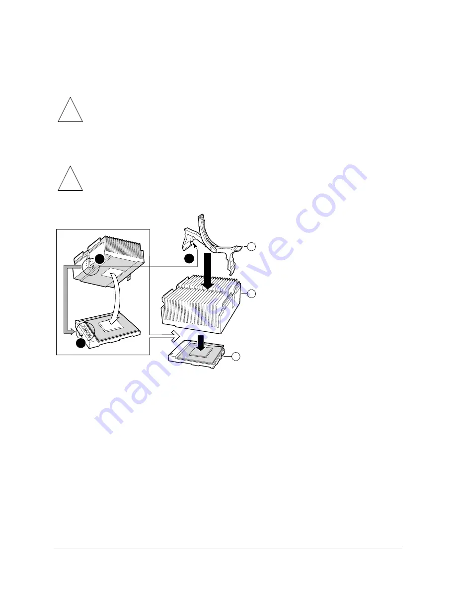
10. Orient the heatsink such that the bottom recessed ledge (also indicated by a slot in the heatsink) is over the 

PGA-370 marking on the socket (see Figure 74). 

11. Gently lower the heatsink in place being careful not to damage the thermal interface material (TIM).  

12. Align the plastic heatsink latching clamp so that the side clip with a pin (1) is over the heatsink slot (2), as shown 

in Figure 74.

Figure 74.   

Installing the Heat Sink and Clip  

13. With the green heatsink clip lever in the upward position, center and push each black clip under the adjacent 

processor socket anchor feature.

!

Caution:

 Misorientation of the heatsink will result in poor contact between heatsink and 

processor. Not only will the processor overheat, but both processor and socket may be 
damaged when clamping the heatsink down. 

!

Caution:

 Incorrect orientation of this clamp will result in damage to the processor socket, 

requiring a main board replacement! User-inflicted damage is not covered under the processor 
or system warranty.

2

3

OM11708A

C

A

B

1

Содержание Cobalt LX50

Страница 1: ...Sun Cobalt LX50 Server User Guide...

Страница 2: ...SCLAIMERS ARE HELD TO BE LEGALLY INVALID Copyright 2002 Sun Microsystems Inc 4150 Network Circle Santa Clara California 95054 U S A Tous droits r serv s Sun Microsystems Inc d tient des droits de prop...

Страница 3: ...are responsible for installing and validating the Sun Cobalt LX50 server Conventions Used in this Manual The following table describes the typographic conventions used in this book Table 1 Typographic...

Страница 4: ...site enables you to access the Sun technical documentation online You can browse the docs sun com archive or search for a specific book title or subject Shell Prompts in Command Examples Table 2 show...

Страница 5: ...le Components 1 4 Optional RJ 45 to DB9 Serial Adapter Kit 1 5 DSR Peripherals Cable 1 5 DCD Modem Cable 1 5 Front EMP Cable 1 5 Preinstalled Software 1 6 Installation Quickstart 1 7 2 Installing the...

Страница 6: ...hassis 2 22 Attach Rail Brackets to Posts 2 23 Attach a Rail Assembly to a Front Bracket 2 23 Attach a Rail Assembly to a Rear Bracket 2 24 Install the Chassis on the Rails 2 25 Connecting the Cables...

Страница 7: ...25 Run HSC Firmware Update 4 25 Run Field Replaceable Unit System Data Record FRU SDR Update2 4 25 Run BIOS Update reboot required 2 4 25 Reboot to Service Partition 4 25 Reboot System 4 25 Restarting...

Страница 8: ...D 6 3 Rear Panel Power Supply Status LED 6 4 Other LEDs 6 4 Server Main Board Fault LEDs 6 5 System ID LEDs 6 6 Power On Self Test POST 6 7 POST Screen Messages 6 7 POST Beep Codes 6 10 BIOS Recovery...

Страница 9: ...ort Summary 7 2 Video Capabilities 7 3 SCSI Capabilities 7 4 Server Management Features 7 4 Power Supply 7 5 Dimensions 7 5 Weight 7 5 Mounting Options 7 5 Environmental 7 6 Ambient Temperature 7 6 Re...

Страница 10: ...Contents x User Guide Sun Cobalt LX50 Server...

Страница 11: ...iew 2 18 Installing the Chassis in the Rack 2 19 Attaching a Chassis Handle to a Center Post 2 20 Fasteners Provided 2 21 Fully Extended Rail Assembly 2 22 Attaching an Inside Rail to the Chassis 2 22...

Страница 12: ...continued 4 22 Platform Confidence Comprehensive Test Progress 4 24 Platform Confidence Comprehensive Test Results 4 24 Removing the Cover 5 3 Bezel Replacement 5 4 Floppy CD ROM Module Replacement 5...

Страница 13: ...2 28 Front RJ 45 Serial 2 Port Adapter Pinout 2 28 Back Serial 2 Port Adapter Pinout 2 31 System Status LED States 6 3 Power Supply Status LED States 6 4 Standard POST Error Messages and Codes 6 7 Ext...

Страница 14: ...xiv User Guide Sun Cobalt LX50 Server...

Страница 15: ...the Sun Cobalt LX50 Server on page 1 1 Contents of the Ship Kit on page 1 3 Replaceable Components on page 1 4 Optional RJ 45 to DB9 Serial Adapter Kit on page 1 5 Preinstalled Software on page 1 6 In...

Страница 16: ...ore details Single or dual processors Six DIMM sockets maximum of 6 GB of main memory Four USB ports Server Management via RJ 45 sockets at front and rear Support for up to three low profile 3 5 inch...

Страница 17: ...0273 1 on CD Sun Linux Installer and Rescue CDs 705 0274 705 0275 705 0291 3 on CD Sun Cobalt LX50 Setup Poster 816 5408 1 printed Binary Code License Agreement and Regulatory Information Packing Lis...

Страница 18: ...ll be replaced by a Sun Service engineer If a CRU needs replacement you can either request a replacement part from Sun or return the entire unit for repair All parts replaced under the system warranty...

Страница 19: ...em See Rear Panel RJ 45 Serial 2 Connector on page 2 30 for more information on how to use this adapter cable Front EMP Cable This cable is wired for connection to the COM port of a laptop or computer...

Страница 20: ...ation on how to use the Sun Linux Installer and Rescue CDs to reinstall Sun Linux and configure the Sun Linux operating environment see the manual titled Sun Linux 5 0 User Guide All software is cover...

Страница 21: ...gure the Sun Cobalt LX50 server Table 6 Installation Quickstart Procedure Step Task Reference 1 Install the Hardware Mount server in the rack Connect the cables See Chapter 2 Installing the Server in...

Страница 22: ...Chapter 1 Introducing the Sun Cobalt LX50 server 1 8 User Guide Sun Cobalt LX50 Server...

Страница 23: ...o decide where you want to configure it In the rack On the bench If you are going to configure the server after it is mounted in the rack proceed to the section titled Precautions on page 2 2 To confi...

Страница 24: ...server power cords are plugged into AC outlets that are part of the rack you must provide proper grounding for the rack itself If server power cords are plugged into wall AC outlets the safety groundi...

Страница 25: ...ly and reliably support the entire weight of a server through the front rack posts Optional Slide Rail Kit see Installing the Server Using the Slide Rail Kit Optional on page 2 21 This mounting method...

Страница 26: ...Required Tools Phillips screwdriver Kit Contents The bracket kit included as standard equipment with the server includes the following items Chassis brackets qty 2 Rear brackets qty 2 L brackets qty...

Страница 27: ...re 3 Removing a Handle from the Chassis Attach Brackets to Chassis 1 Place a chassis bracket along one side of the chassis in the front mount position Figure 4 A 2 Align the holes B in the bracket wit...

Страница 28: ...osition B Bracket holes C Chassis tabs D 6 32 x 3 16 inch screw Attach Disks to Chassis 1 Place a chassis disk at the side of the chassis towards the rear see Figure 5 A 2 Install screw B and tighten...

Страница 29: ...Do not completely tighten the screws leave them loose enough to allow insertion of the brackets in step 2 2 Insert the slotted foot of a rear bracket C between each nut bar and post 3 Align the face o...

Страница 30: ...assis in the Rear Brackets A Chassis disk B Rear bracket 2 Slide the chassis toward the rear of the rack until the front of the chassis brackets contact the front posts 3 Attach the chassis brackets F...

Страница 31: ...the Server Using the Bracket Kit User Guide Sun Cobalt LX50 Server 2 9 Figure 8 Attaching a Front Bracket to a Front Post A Chassis bracket B Front post C 10 32 x 1 2 inch screw with washers D Nut ba...

Страница 32: ...e and the chassis bracket 4 Install and tighten screw C to secure the handle 5 In the same manner attach the other handle to the opposite side 6 Replace the bezel You have completed the installation o...

Страница 33: ...oles B in the bracket with the tabs C on the chassis and place the bracket against the chassis 3 Slide the bracket as far as it will go toward the front of the chassis 4 Fasten the bracket to the chas...

Страница 34: ...ackside of the center post C 2 Attach the L bracket to the center post using the screws B supplied with your rack Do not fully tighten at this time 3 In the same manner attach an L bracket to the othe...

Страница 35: ...L Brackets Inserted into Chassis Mounting Brackets Rear View 4 Slide the chassis toward the rear of the rack until the front of the chassis mounting brackets contact the front of the center posts 5 U...

Страница 36: ...nstalling the Server in a Rack 2 14 User Guide Sun Cobalt LX50 Server Figure 13 Installing the Chassis in the Rack A Chassis bracket in mid mount position B L bracket C Screw supplied by rack manufact...

Страница 37: ...ing your chassis using this option is not recommended for use in most rack systems In fact the front mount method is highly discouraged as most racks are unable to safely and reliably support the enti...

Страница 38: ...with the tabs C on the chassis and place the bracket against the chassis 3 Slide the bracket as far as it will go toward the front of the chassis 4 Attach the bracket to the chassis using screw D 5 In...

Страница 39: ...ckside of the center post C 2 Attach the L bracket to the center post using the screws B supplied with your rack Do not fully tighten at this time 3 In the same manner attach an L bracket to the other...

Страница 40: ...fit tightly into the chassis brackets C Figure 17 L Brackets Inserted into Chassis Mounting Brackets Rear View 4 Slide the chassis toward the rear of the rack until the front of the chassis brackets...

Страница 41: ...e Server Using the Bracket Kit User Guide Sun Cobalt LX50 Server 2 19 Figure 18 Installing the Chassis in the Rack A Chassis bracket in front mount position B L bracket C Screw supplied by rack manufa...

Страница 42: ...t 3 Install a spacer B between the handle and the bracket 4 Install and tighten screw C to secure the handle 5 In the same manner attach the other handle to the opposite side 6 Replace the bezel Figur...

Страница 43: ...al equipment includes the following items Slide rail assemblies qty 2 Rail brackets qty 4 Fastener pack qty 1 see Figure 20 Figure 20 Fasteners Provided Remove the Inside Rails 1 Fully extend a rail a...

Страница 44: ...place the rail against the chassis 3 Slide the rail as far as it will go toward the front of the chassis to engage the tabs 4 Fasten the rail to the chassis using one screw B at the front of the chass...

Страница 45: ...acket 1 Position a rail assembly middle and outer rails with its black plastic end caps toward the rear of the rack and its outer rail closest to the brackets 2 Align the front screw hole Figure 24 C...

Страница 46: ...e rail toward the front Figure 25 until the rear bracket area is accessible 2 Attach the rear end of the outer rail B to the rear bracket A with at least one screw C If possible attach at two places 3...

Страница 47: ...ended 2 With the chassis front facing you lift the chassis and carefully insert the rails attached to the chassis in the extended rails 3 Slide the chassis toward the rear of the cabinet until the rai...

Страница 48: ...rver in a Rack 2 26 User Guide Sun Cobalt LX50 Server Figure 27 Releasing the Extension Locks 5 Slide the chassis all the way into the rack until the chassis handles are against the front posts A Fing...

Страница 49: ...is set by default to redirect BIOS bootup and Linux Loader LILO messages to the serial port The default communications settings for the serial console ports on the server are 9600 bps 8 data bits 1 st...

Страница 50: ...t connect or PC to PC serial communication either an 8 pin RJ 45 to DB9 adapter or a cable supporting both DB 9 and RJ 45 connectors is necessary Table 8 provides a pinout for the front RJ 45 to DB9 a...

Страница 51: ...B 4 connector RJ 45 NIC 1 and NIC 2 Connectors The server supports two 10BASE T 100BASE TX Network Interface Controllers NICs The NIC interfaces support the following features Integrated IEEE 802 3 10...

Страница 52: ...ver market to access the server management features of the server To give support for either of two serial configuration standards used by serial port concentrators the J6A2 jumper block located on th...

Страница 53: ...opriate RJ 45 to DB9 adapter Figure 32 J6A2 Jumper Block Configured for DCD Signal pin 7 connected to DCD Table 9 Back Serial 2 Port Adapter Pinout RJ 45 Signal Abbr DB9 1 Request to Send RTS 7 2 Data...

Страница 54: ...onnector supports a standard high density 68 pin connector Use only shielded Ultra 160 LVDS rated cables for connection to external SCSI drives Video Connector The Sun Cobalt LX50 server provides an A...

Страница 55: ...Board see the additional information contained in Chapter 6 Troubleshooting the Server The pushbuttons and LEDs on the front and rear panels are described in the following sections Front Panel LEDs an...

Страница 56: ...lar systems The System ID LED is illuminated when the system ID button located on the front panel is pressed If activated by the front panel pushbutton the LED remains on until the pushbutton is depre...

Страница 57: ...panel It can provide a mechanism for identifying one system out of a group of identical systems This can be particularly useful if the server is used in a rack mount chassis in a high density multiple...

Страница 58: ...Chapter 3 Controls and Indicators 3 4 User Guide Sun Cobalt LX50 Server...

Страница 59: ...n page 4 26 Setting the Jumper Positions Two jumpers on the Main Board are preset by default to the positions that satisfy most serial port configurations They are located at the rear of the server on...

Страница 60: ...d to the video port or to a serial console attached to the front or rear RJ 45 serial console ports The server is configured by default to initially send BIOS and kernel messages to both the serial co...

Страница 61: ...artition a DOS partition allowing setup configuration and server testing F12 to boot from the Network BIOS Setup Utility F2 Press F2 to enter the BIOS Setup Utility The main BIOS Setup Utility screen...

Страница 62: ...e 38 Use this screen to restore the boot sequence if necessary Figure 38 Default Boot Sequence You can always restore all of the default BIOS settings by scrolling to the Exit menu item along the top...

Страница 63: ...led Screen PXE Pre boot Execution Environment is a method by which the server can booted from a remote server This allows the system to boot without any knowledge of the Operating System on the server...

Страница 64: ...ing the default option linux is automatically selected after about five seconds This option is also selected if you press Enter before the five seconds is up You may also manually select one of the op...

Страница 65: ...as an interface to a serial port concentrator allowing for remote access to the server s Emergency Management Port EMP The serial connector on the front panel can be used as a direct connect to the EM...

Страница 66: ...e boot screen information is sent both to the VGA and serial ports and you are presented with the following choices linux linux up linux serial linux up serial To direct all of the messages to the ser...

Страница 67: ...Using the Service Partition Menu When you press F4 at the initial bootup screen the Service Partition Menu appears see Figure 43 Figure 43 Service Partition Menu There are three main menu items acros...

Страница 68: ...page 4 12 FRU SDR Load Utility choosing this option creates one diskette that allows you to run the FRU SDR Load Utility in the same way that you run it from the service partition or from the diagnost...

Страница 69: ...d brings up the submenu shown in Figure 45 Figure 45 System Utilities Submenu The following submenus are available Run System Setup Utility Run System Diagnostic Test Run BMC Firmware Update Run HSC F...

Страница 70: ...stem Setup Utility to run system setup The System Setup Utility main window appears see Figure 46 Figure 46 SSU Main Window The System Setup Utility SSU allows you to configure the following User Pref...

Страница 71: ...ltiboot Add in Window To change boot priorities select a boot device and use the Move Down and Move Up buttons to move the device boot priority Configuring Security The Password Authorization feature...

Страница 72: ...SDR Manager allows you to view the current sensor data for the system save the SDR data to a file and view SDR information previously saved to a file The SDR data is saved in standard SDR format To m...

Страница 73: ...dow The Platform Event Manager main window appears You can click on the buttons in this window to perform platform management Run System Diagnostic Test Select Run System Diagnostic test to bring up t...

Страница 74: ...r On Self Test POST CPU Test s Symmetric Multiprocessing SMP Processor 0 Test Symmetric Multiprocessing SMP Processor 1 Test Hard Disk Drive Test s Cache Memory Test s DIMM Memory Test To run the Quic...

Страница 75: ...isplay the remaining results of the configuration testing see Figure 52 Figure 52 Platform Confidence Quick Test Hardware Test Configuration second screen 3 If the hardware configuration does not matc...

Страница 76: ...LX50 Server Several entries are displayed and scroll past on the screen showing the test progress see Figure 53 Figure 53 Platform Confidence Quick Test Progress When the testing is done the results a...

Страница 77: ...sensor readings see Figure 55 Figure 55 Platform Confidence Quick Test Sensor Readings first screen 6 Press any key to see the remaining sensor readings see Figure 56 Figure 56 Platform Confidence Qui...

Страница 78: ...ectories to C PCT 3 Type the following command Type RESULT LOG more A portion of the RESULT LOG file is displayed each time you press a key In this way you can see the results which are divided into t...

Страница 79: ...Using the Service Partition Menu User Guide Sun Cobalt LX50 Server 4 21 Figure 58 Sample RESULT LOG continued...

Страница 80: ...Chapter 4 Powering On and Configuring the Server 4 22 User Guide Sun Cobalt LX50 Server Figure 59 Sample RESULT LOG continued...

Страница 81: ...oller Test Super I O Controller Test DMA Controller Test Baseboard Management Controller Test Comm Port 1 Controller Test Comm Port 2 Controller Test Adaptec SCSI Controller Test Parallel Port Control...

Страница 82: ...r the Quick Test Figure 60 Platform Confidence Comprehensive Test Progress When the testing is done the results are summarized see Figure 61 Figure 61 Platform Confidence Comprehensive Test Results 4...

Страница 83: ...r optional fields that are left blank when the system is shipped from the factory When you run the update make sure you choose the following at the appropriate prompt Main Board supports SCSI drives S...

Страница 84: ...tops you must log in as root first The Ctrl Alt Del key combination works for both PS 2 and USB keyboards shutdown h now type this to initiate an orderly shutdown and halt the server You may then pres...

Страница 85: ...engineers only If a Field Replaceable Unit FRU needs replacement contact your local Sun Sales representative who will put you in contact with the Sun Enterprise Service branch for your area You can a...

Страница 86: ...Errors on page 6 2 Platform Confidence Test see Platform Confidence Test PCT on page 6 2 System Setup Utility see System Setup Utility SSU on page 6 2 Safety Before You Remove the Cover Before removi...

Страница 87: ...cover follow these steps 1 While pressing the blue latch button A with your left thumb push down on the top cover and slide it back using the heel of your right hand on the black pad see Figure 62 Fi...

Страница 88: ...erals when a front bezel is installed grasp the bezel at the finger hole on the right side and gently pull it towards you unhinging it at the left until it unsnaps from the chassis Replace the bezel u...

Страница 89: ...mm more to fully engage the connectors 6 Rotate the handle bar down 7 Reinstall the bezel Caution A CD ROM drive FDD module is NOT hot swappable Before replacing it you must first take the server out...

Страница 90: ...ons Caution Before touching or replacing any component inside the LX50 server disconnect all external cables and follow the instructions in Safety Before You Remove the Cover on page 5 2 and Removing...

Страница 91: ...t module onto the chassis floor and slide it toward the front of the chassis until the edge connector is fully inserted in the power distribution board connector Caution Your Sun Cobalt LX50 server do...

Страница 92: ...a HDD assembly drive mounted on a carrier or a carrier with an air baffle installed Caution You must remove power from the Sun Cobalt LX50 server before attempting to remove or insert a HDD Be sure t...

Страница 93: ...its wrapper and place it on an anti static surface 7 Install the new HDD assembly into the drive bay by inserting the tab end B of the retention lever A into the housing slot C and gently closing the...

Страница 94: ...the flex cable auxiliary power cable and SCSI cables are routed under where you will be installing the air baffle 2 Aligning pin A with the board mounting hole position the air baffle over the white s...

Страница 95: ...all 9 Lower the module to the chassis floor Ensure it is situated between the raised guides not on top of them 10 Press down on the left end of the module until tab B fits into the chassis slot C 11 P...

Страница 96: ...Chapter 5 Maintaining the Server 5 12 User Guide Sun Cobalt LX50 Server Figure 69 Fan Module Replacement OM11681A A D B C...

Страница 97: ...p B on the riser card retention bracket 6 Pull the PCI card out of the riser card slot C 7 Install the new PCI add in card on the riser Caution Before touching or replacing any component inside the LX...

Страница 98: ...nt batteries Caution Press the riser card straight down into the slot Tipping it in the slot while installing it may damage the riser card or board slot Note The Comprehensive Test should be run after...

Страница 99: ...Safety Before You Remove the Cover on page 5 2 and Removing and Replacing the Cover on page 5 3 Always place the server on a grounded ESD pad and wear a properly grounded antistatic wrist strap The se...

Страница 100: ...clamp bracket upwards 3 Gently lift the heatsink and the clamp 4 Grasp the end of the zero insertion force arm and bend it out slightly until it disengages from the socket tab 5 Raise the zero insert...

Страница 101: ...sits flush and level on the socket 9 Lower the locking bar completely until it locks see Figure 73 Caution If you are installing a processor removed from a different server you must prepare the proce...

Страница 102: ...Chapter 5 Maintaining the Server 5 18 User Guide Sun Cobalt LX50 Server Figure 73 Inserting the Processor and Lowering the Locking Bar OM11712...

Страница 103: ...s shown in Figure 74 Figure 74 Installing the Heat Sink and Clip 13 With the green heatsink clip lever in the upward position center and push each black clip under the adjacent processor socket anchor...

Страница 104: ...hown in Figure 75 until the clip lever A contacts tab B Figure 75 Closing the Locking Lever 15 Verify the heatsink clamp has latched correctly on each side Note The Comprehensive Test should be run af...

Страница 105: ...the locking bar completely until it locks see Figure 76 Caution The procedure below is for the attention of qualified service engineers only Before touching or replacing any component inside the LX50...

Страница 106: ...material TIM 8 Align the plastic heatsink latching clamp so that the side clip with a pin 1 is over the heatsink slot 2 as shown in Figure 77 Caution Misorientation of the heatsink will result in poor...

Страница 107: ...he adjacent processor socket anchor feature 10 Slowly close the green clip lever as shown in Figure 78 until the clip lever A contacts tab B Figure 78 Closing the Locking Lever 11 Verify the heatsink...

Страница 108: ...emove the fan module see Fan Module on page 5 11 10 Disconnect both ends of all remaining cables 11 Remove the SCSI backplane board 12 Remove the power distribution board the board the power supply mo...

Страница 109: ...Remove the replacement server board from its packaging and antistatic bag 19 While placing the board on the chassis standoffs carefully position the board I O connectors in the rear chassis I O openin...

Страница 110: ...if you have no additional work to do inside the chassis 31 Insert the removed board into the antistatic bag from the new board and insert it into the box for return to Sun Microsystems A return shipp...

Страница 111: ...e server board and remove it 5 Disconnect the Floppy FP IDE flex circuit cable from the SCSI backplane 6 Disconnect the Floppy FP IDE flex circuit cable to the server board and remove Caution The proc...

Страница 112: ...cable to the main board Connect the USB cable to the front panel board Fasten the USB cable to the chassis clip 4 Connect the Floppy FP IDE flex circuit cable to the server board 5 Connect the Floppy...

Страница 113: ...that must be followed when disassembling heatsinks from processors see Replacing a CPU and Heatsink on page 5 15 Caution The procedure below is for the attention of qualified service engineers only Be...

Страница 114: ...Chapter 5 Maintaining the Server 5 30 User Guide Sun Cobalt LX50 Server...

Страница 115: ...t and isolate faulty components within the Sun Cobalt LX50 server The chapter contains these sections Diagnosing System Errors on page 6 2 Status LEDs on page 6 3 Server Main Board Fault LEDs on page...

Страница 116: ...CT The PCT is used to test major subsystems of the system board System Setup Utility SSU The SSU is used to read the System Event Log SEL Platform Confidence Test PCT The PCT consists of up to 31 test...

Страница 117: ...system The system is unable to power up due to incorrectly installed processor s or processor incompatibility A satellite controller such as the HSC or another IMPI capable device such as an add in se...

Страница 118: ...n on how to isolate the server component responsible for any of the critical non critical or degraded conditions listed above Rear Panel Power Supply Status LED The rear panel power supply status LED...

Страница 119: ...each of the processor sockets If the server Baseboard Management Controller BMC detects a fault in any processor the corresponding LED illuminates Memory Fault LEDs A fault indicator LED is located ne...

Страница 120: ...an be illuminated by the Baseboard Management Controller BMC either by pressing a button on the chassis front panel or through server management software When the button is pressed on the front panel...

Страница 121: ...y be malfunctioning All POST errors and warnings are logged in the System Event Log SEL See Managing the System Event Log on page 4 14 for more details on the SEL Note All POST errors are logged to th...

Страница 122: ...s 143 PCI IRQ Allocation Error Yes 144 Shadow of PCI ROM Failed Yes 145 PCI ROM not found Yes 146 Insufficient Memory to Shadow PCI ROM Yes Table 13 Extended POST Error Messages and Codes Error Code E...

Страница 123: ...bus ratio Processor Cache disabled Yes 8192 L2 Cache size mismatch Yes 8193 CPUID Processor Stepping are different Yes 8194 CPUID Processor Family are different Yes 8195 Front Side Bus Speed mismatch...

Страница 124: ...er control failure Table 15 BIOS Generated POST Beep Codes Beep Code Error Message Description 1 Refresh timer failure The memory refresh circuitry on the Main Board is faulty 2 Parity error Parity ca...

Страница 125: ...f Off Off G Memory mixed type detected 3 02h Off Off G Off EDO is not supported 3 03h Off Off G G First row memory test failure 3 04h Off G Off Off Mismatched DIMMs in a row 3 05h Off G Off G Base mem...

Страница 126: ...reen LEDs are lit resulting in an amber color Likewise if both bits are clear then the red and green LEDs are off During the POST process each light sequence represents a specific Port 80 POST code If...

Страница 127: ...lization before CMOS initialization 19h G Off Off A Init System Timer the 8254 timer test is over Starting the memory refresh test next 1Ah G Off G R Check Refresh Toggle the memory refresh line is to...

Страница 128: ...ower on message next 37h Off G A A Initialize language module Display splash logo 37h Off G A A Display Sign On Message BIOS ID and processor information 38h G Off R R Detect USB mouse initializing th...

Страница 129: ...play IDE mass storage devices 17h Off G G A Display USB mass storage devices 85h R G Off G Report the first set of POST errors to error manager 86h R G G Off Boot Password Check the password was check...

Страница 130: ...timeout settings in keyboard controller A7h R G A G Processor initialization before boot A7h R G A G Copy required language strings to shadow RAM AAh A Off A Off Clear video screen 00h Off Off Off Of...

Страница 131: ...w according to your location United States 800 526 0484 UK Tel 44 8760 600 3222 France Tel 33 1 34 03 50 80 Germany Tel 49 1805 20 22 41 Italy Tel 39 02 92595228 Free 800605228 Spain Tel 011 34 91 767...

Страница 132: ...Chapter 6 Troubleshooting the Server 6 18 User Guide Sun Cobalt LX50 Server...

Страница 133: ...de Bus Supports CPU Speeds to 1 4 GHz Chipset ServerWorks ServerSet III HE SL Chipset HE SL North Bridge CIOB20 I O Bridge CSB5 South Bridge Supports up to six PC 133 compliant registered ECC SDRAM DI...

Страница 134: ...ler Zero Channel RAID ZCR adapter support Segment C 64 bit 66 33 MHz 3 3 V P64 C supporting the following device One Low Profile PCI 2 2 expansion slot LPC Low Pin Count bus segment with two embedded...

Страница 135: ...ed 1280x1024 70 72 Supported Supported Supported 1600x1200 60 66 Supported Supported Supported Supported 1600x1200 76 85 Supported Supported Supported 1600x1200 60 66 76 85 Supported 3D Mode Refresh R...

Страница 136: ...er provides active terminators termination voltage a resettable fuse and a protection diode for both SCSI channels By design the on board termination is always enabled No ability is provided to disabl...

Страница 137: ...ply Dual redundant fans Status LED Dimensions Height 1 693 in 43 mm Width 16 93 in 430 mm Depth 23 89 in 609 2 mm Weight Approximately 11 8 kg 26 lbs unpacked 2 drive server Approximately 40 lbs packa...

Страница 138: ...umidity Operating Humidity 10 to 90 at 27 C non condensing Non Operating Humidity 93 at 38 C non condensing Vibration Operating Vibration 0 15 G z axis 0 10 G x and y axis 5 to 500 Hz sine Non Operati...

Отзывы: