Section 1
SAFETY
2
or at a minimum of at least weekly to make sure it
is not blocked, clogged, obstructed or otherwise
disabled.
DO NOT
change the factory setting of the
relief valve.
M.
If the compressor is installed in an enclosed
area, it is necessary to vent the relief valve to the
outside of the structure or to an area of non-expo-
sure.
1.4 FIRE AND EXPLOSION
When installing a Base Load Transfer (BLT)
System, remove jumpers between 16-17 & 18-19
(Dual Control Compressors) so the other com-
pressor does not backfeed defeating the shut-
down circuitry.
A.
Clean up spills of lubricant or other combustible
substances immediately, if such spills occur.
B.
Shut off the compressor and allow it to cool.
Then keep sparks, flames and other sources of igni-
tion away and
DO NOT
permit smoking in the vicin-
ity when checking or adding lubricant or when refill-
ing air line anti-icer systems with antifreeze com-
pound.
C. DO NOT
permit fluids, including air line anti-icer
system antifreeze compound or fluid film to accu-
mulate on, under, or around acoustical material, or
on any external surfaces of the air compressor or
on internal surfaces of the enclosure. Wipe down
using an aqueous industrial cleaner or steam-clean
as required. If necessary, remove acoustical mate-
rial, clean all surfaces and then replace acoustical
material. Any acoustical material with a protective
covering that has been torn or punctured should be
replaced immediately to prevent accumulation of
liquids or fluid film within the material.
DO NOT
use
flammable solvents for cleaning purposes.
D.
Disconnect and lock out all power at source prior
to attempting any repairs or cleaning of the com-
pressor or of the inside of the enclosure, if any.
E.
Keep electrical wiring, including all terminals and
pressure connectors in good condition. Replace
any wiring that has cracked, cut abraded or other-
wise degraded insulation, or terminals that are
worn, discolored or corroded. Keep all terminals
and pressure connectors clean and tight.
F.
Keep grounded and/or conductive objects such
as tools away from exposed live electrical parts
such as terminals to avoid arcing which might serve
as a source of ignition.
G.
Remove any acoustical material or other materi-
al that may be damaged by heat or that may sup-
port combustion and is in close proximity, prior to
attempting weld repairs.
H.
Keep suitable fully charged fire extinguisher or
extinguishers nearby when servicing and operating
the compressor.
I.
Keep oily rags, trash, leaves, litter or other com-
bustibles out of and away from the compressor.
J. DO NOT
operate the compressor without proper
flow of cooling air or water or with inadequate flow
of lubricant or with degraded lubricant.
K. DO NOT
attempt to operate the compressor in
any classification of hazardous environment unless
the compressor has been specially designed and
manufactured for that duty.
1.5 MOVING PARTS
A.
Keep hands, arms and other parts of the body
and also clothing away from couplings, fans and
other moving parts.
B. DO NOT
attempt to operate the compressor with
the fan, coupling or other guards removed.
C.
Wear snug-fitting clothing and confine long hair
when working around this compressor, especially
when exposed to hot or moving parts.
D.
Keep access doors, if any, closed except when
making repairs or adjustments.
E.
Make sure all personnel are out of and/or clear of
the compressor prior to attempting to start or oper-
ate it.
F.
Disconnect and lock out all power at source and
verify at the compressor that all circuits are de-
energized to minimize the possibility of accidental
start-up or operation, prior to attempting repairs or
adjustments. This is especially important when
compressors are remotely controlled.
G.
Keep hands, feet, floors, controls and walking
surfaces clean and free of fluid, water, or other liq-
uids to minimize the possibility of slips and falls.
1.6 HOT SURFACES, SHARP EDGES AND SHARP
CORNERS
A.
Avoid bodily contact with hot fluid, hot coolant,
hot surfaces and sharp edges and corners.
B.
Keep all parts of the body away from all points of
air discharge.
C.
Wear personal protective equipment including
gloves and head covering when working in, on or
around the compressor.
D.
Keep a first aid kit handy. Seek medical assis-
tance promptly in case of injury.
DO NOT
ignore
Содержание LS-32
Страница 6: ...NOTES...
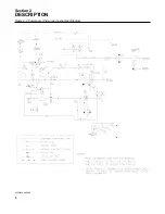
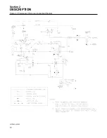
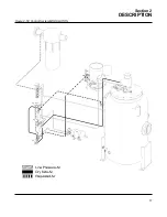
Страница 14: ...Section 2 DESCRIPTION 8 Figure 2 2 Compressor Piping and Instrument Diagram 02250140 998R02...
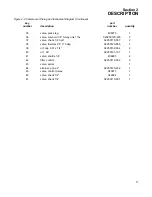
Страница 16: ...Section 2 DESCRIPTION 10 Figure 2 2 Compressor Piping and Instrument Diagram 02250140 998R02...
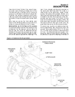
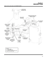
Страница 21: ...Section 2 DESCRIPTION 15 Figure 2 5A Control System KEY COMPONENTS...
Страница 22: ...Section 2 DESCRIPTION 16 Figure 2 5B Control System START...
Страница 23: ...Section 2 DESCRIPTION 17 Figure 2 5C Control System MODULATION...
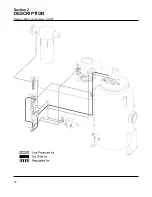
Страница 24: ...Section 2 DESCRIPTION 18 Figure 2 5D Control System UNLOAD...
Страница 25: ...Section 2 DESCRIPTION 19 Figure 2 5E Control System FULL LOAD...
Страница 28: ...Section 3 SPECIFICATIONS 22 Figure 3 2 Identification LS 32 Air cooled 02250140 997R01...
Страница 32: ...Section 5 SUPERVISOR CONTROLLER 26 Figure 5 1 Supervisor Control Panel...
Страница 44: ...38 NOTES...
Страница 56: ...50 NOTES...
Страница 59: ...53 NOTES...
Страница 60: ...Section 8 ILLUSTRATIONS AND PARTS LIST 54 8 3 MOTOR COMPRESSOR FRAME AND PARTS 02250140 989R01...
Страница 62: ...Section 8 ILLUSTRATIONS AND PARTS LIST 56 8 3 MOTOR COMPRESSOR FRAME AND PARTS 02250140 989R01...
Страница 64: ...Section 8 ILLUSTRATIONS AND PARTS LIST 58 8 4 AIR INLET SYSTEM 02250140 990R02...
Страница 66: ...Section 8 ILLUSTRATIONS AND PARTS LIST 60 8 4 AIR INLET SYSTEM 02250140 990R02...
Страница 68: ...Section 8 ILLUSTRATIONS AND PARTS LIST 62 8 5 FLUID COOLING SYSTEM AIR COOLED 02250140 994R00...
Страница 70: ...Section 8 ILLUSTRATIONS AND PARTS LIST 64 8 5 FLUID COOLING SYSTEM AIR COOLED 02250140 994R00...
Страница 72: ...Section 8 ILLUSTRATIONS AND PARTS LIST 66 8 6 AIR PIPING SYSTEM AIR COOLED 02250140 992R01...
Страница 74: ...Section 8 ILLUSTRATIONS AND PARTS LIST 68 8 6 AIR PIPING SYSTEM AIR COOLED 02250140 992R01...
Страница 76: ...Section 8 ILLUSTRATIONS AND PARTS LIST 70 02250140 993R01 8 7 FLUID PIPING SYSTEM AIR COOLER...
Страница 78: ...Section 8 ILLUSTRATIONS AND PARTS LIST 72 02250140 993R01 8 7 FLUID PIPING SYSTEM AIR COOLER...
Страница 80: ...Section 8 ILLUSTRATIONS AND PARTS LIST 74 02250140 991R00 8 8 SUMP AND PARTS...
Страница 82: ...Section 8 ILLUSTRATIONS AND PARTS LIST 76 02250140 991R00 8 8 SUMP AND PARTS...
Страница 84: ...Section 8 ILLUSTRATIONS AND PARTS LIST 78 8 9 SULLICON CONTROL 02250134 158R00...
Страница 86: ...Section 8 ILLUSTRATIONS AND PARTS LIST 80 8 10 COMPRESSOR ACTUATOR...
Страница 88: ...Section 8 ILLUSTRATIONS AND PARTS LIST 82 8 11 PNEUMATIC CONTROLS 02250140 996R00...
Страница 90: ...Section 8 ILLUSTRATIONS AND PARTS LIST 84 8 11 PNEUMATIC CONTROLS 02250140 996R00...
Страница 92: ...Section 8 ILLUSTRATIONS AND PARTS LIST 86 8 11 PNEUMATIC CONTROLS 02250140 996R00...
Страница 94: ...Section 8 ILLUSTRATIONS AND PARTS LIST 88 8 12 CONTROL BOX SOLID STATE 02250122 005R04...
Страница 96: ...Section 8 ILLUSTRATIONS AND PARTS LIST 90 8 13 CONTROL BOX FULL VOLTAGE 02250122 511R04...
Страница 98: ...Section 8 ILLUSTRATIONS AND PARTS LIST 92 8 14 CONTROL BOX WYE DELTA 02250122 516R08...
Страница 100: ...Section 8 ILLUSTRATIONS AND PARTS LIST 94 8 15 ENCLOSURE AIR COOLED 02250140 995R00...
Страница 102: ...Section 8 ILLUSTRATIONS AND PARTS LIST 96 8 15 ENCLOSURE AIR COOLED 02250140 995R00...
Страница 104: ...Section 8 ILLUSTRATIONS AND PARTS LIST 98 8 16 DECAL GROUP...
Страница 106: ...Section 8 ILLUSTRATIONS AND PARTS LIST 100 8 16 DECAL GROUP...
Страница 108: ...Section 8 ILLUSTRATIONS AND PARTS LIST 102 8 16 DECAL GROUP...
Страница 110: ...Section 8 ILLUSTRATIONS AND PARTS LIST 104 8 17 DECAL LOCATIONS...
Страница 112: ...Section 8 ILLUSTRATIONS AND PARTS LIST 106 8 18 DECAL LOCATIONS ENCLOSURE...
Страница 114: ...Section 8 ILLUSTRATIONS AND PARTS LIST 108 8 19 DECAL LOCATIONS CONTROL BOX...
Страница 116: ...Section 8 ILLUSTRATIONS AND PARTS LIST 110 02250140 999R00 8 20 WIRING DIAGRAM AIR COOLED CUSTOMER SUPPLIED STARTER...
Страница 117: ...111 NOTES...


