Section 7
MAINTENANCE
42
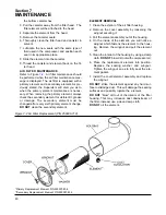
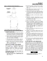
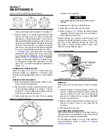
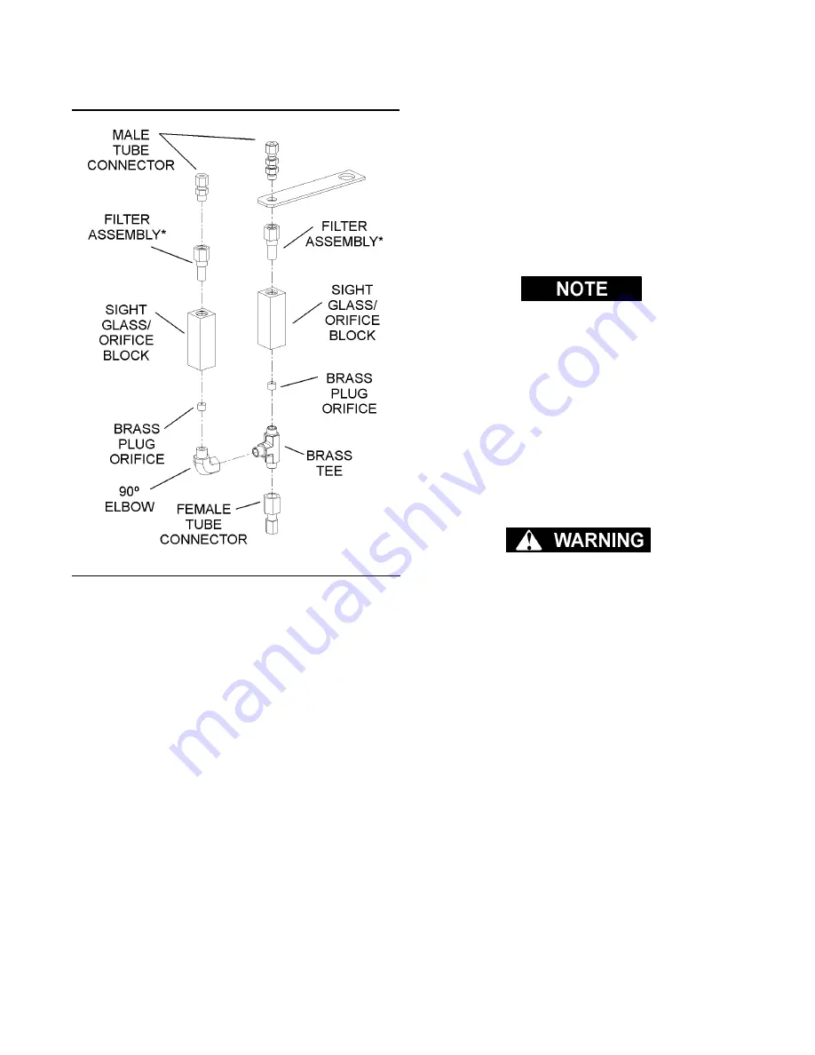
1. Disconnect the tubes at the tops of the sight
glass assemblies.
2. Unscrew male connector (for left-side glass), or
the straight thread tube connector (for right-side
glass) from sight glass/orifice blocks.
3. Remove used filter assembly, and replace with
new assembly.
4. Coat/lubricate the O-rings will silicone grease.
5. Reattach the connectors to the sight glass/orifice
blocks.
DIFFERENTIAL
PRESSURE REGULATOR
ADJUSTMENT
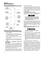
. The differential pres-
sure regulators are adjusted by loosening the jam
nut on the end of the cone shaped cover of the
pressure regulator. When the jam nut is loose, turn
the adjusting screw clockwise to increase or coun-
terclockwise to decrease the setting.
Above 100 psig (6.9 bar), the spiral valve regulator
should allow pressure to flow into the chamber of
the spiral valve actuator. The spiral valve should
start to rotate at this time.
At approximately 108 psig (7.5 bar), the Sullicon
regulator should allow pressure to flow into the con-
trol chamber of the Sullicon Control. The Sullicon
Control level should start to move at this time. Cycle
the Control System several times and recheck all
pressure settings.
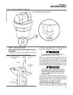
COMPRESSOR DRIVE COUPLING
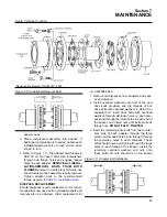
The performance and life of couplings depend
largely upon how you install and maintain them.
Before installing couplings, make certain that
foundations of equipment to be connected meet
requirements of
must be aligned after installation and prior to ini-
tial start-up of the compressor.
The use of stainless steel shims under the motor
feet is recommended. Measuring misalignment and
positioning equipment within alignment tolerances
is simplified with an alignment computer. These cal-
culations can also be done graphically or mathe-
matically.
ANNUAL MAINTENANCE- DRIVE COUPLING
Disconnect all power at source before attempting
maintenance or adjustments.
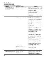
from
are exceeded,
realign coupling to installation limits.
2. Check outer blades of discpacks near bushings
for fatigue cracks. Discpacks can be checked
while coupling is in operation by using a strobe
light. Replace cracked discpacks and recheck
alignment. A slight bowing or “S”-like distortion is
normal.
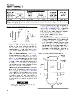
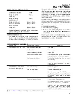
3. Check tightening torques of all drive bolts.
Standard mechanics tools, torque wrenches, a
straight edge and feeler gauges or dial indicators
and brackets and micrometers are required to
install couplings. A 17mm end wrench is required
for shrink disc locking screws. For best results use
a dial indicator to check final alignment and make
certain bolts are tightened to the required elonga-
tion or torque listed in
The drive bolts have been factory tightened to the
required elongation indicated in
, and should not be disturbed.
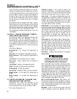
Figure 7-4 Oil Return/Sight Glass
*Replacement Filter Assembly P/N 02250117-782
Содержание LS-32
Страница 6: ...NOTES...
Страница 14: ...Section 2 DESCRIPTION 8 Figure 2 2 Compressor Piping and Instrument Diagram 02250140 998R02...
Страница 16: ...Section 2 DESCRIPTION 10 Figure 2 2 Compressor Piping and Instrument Diagram 02250140 998R02...
Страница 21: ...Section 2 DESCRIPTION 15 Figure 2 5A Control System KEY COMPONENTS...
Страница 22: ...Section 2 DESCRIPTION 16 Figure 2 5B Control System START...
Страница 23: ...Section 2 DESCRIPTION 17 Figure 2 5C Control System MODULATION...
Страница 24: ...Section 2 DESCRIPTION 18 Figure 2 5D Control System UNLOAD...
Страница 25: ...Section 2 DESCRIPTION 19 Figure 2 5E Control System FULL LOAD...
Страница 28: ...Section 3 SPECIFICATIONS 22 Figure 3 2 Identification LS 32 Air cooled 02250140 997R01...
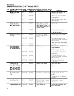
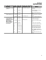
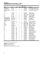
Страница 32: ...Section 5 SUPERVISOR CONTROLLER 26 Figure 5 1 Supervisor Control Panel...
Страница 44: ...38 NOTES...
Страница 56: ...50 NOTES...
Страница 59: ...53 NOTES...
Страница 60: ...Section 8 ILLUSTRATIONS AND PARTS LIST 54 8 3 MOTOR COMPRESSOR FRAME AND PARTS 02250140 989R01...
Страница 62: ...Section 8 ILLUSTRATIONS AND PARTS LIST 56 8 3 MOTOR COMPRESSOR FRAME AND PARTS 02250140 989R01...
Страница 64: ...Section 8 ILLUSTRATIONS AND PARTS LIST 58 8 4 AIR INLET SYSTEM 02250140 990R02...
Страница 66: ...Section 8 ILLUSTRATIONS AND PARTS LIST 60 8 4 AIR INLET SYSTEM 02250140 990R02...
Страница 68: ...Section 8 ILLUSTRATIONS AND PARTS LIST 62 8 5 FLUID COOLING SYSTEM AIR COOLED 02250140 994R00...
Страница 70: ...Section 8 ILLUSTRATIONS AND PARTS LIST 64 8 5 FLUID COOLING SYSTEM AIR COOLED 02250140 994R00...
Страница 72: ...Section 8 ILLUSTRATIONS AND PARTS LIST 66 8 6 AIR PIPING SYSTEM AIR COOLED 02250140 992R01...
Страница 74: ...Section 8 ILLUSTRATIONS AND PARTS LIST 68 8 6 AIR PIPING SYSTEM AIR COOLED 02250140 992R01...
Страница 76: ...Section 8 ILLUSTRATIONS AND PARTS LIST 70 02250140 993R01 8 7 FLUID PIPING SYSTEM AIR COOLER...
Страница 78: ...Section 8 ILLUSTRATIONS AND PARTS LIST 72 02250140 993R01 8 7 FLUID PIPING SYSTEM AIR COOLER...
Страница 80: ...Section 8 ILLUSTRATIONS AND PARTS LIST 74 02250140 991R00 8 8 SUMP AND PARTS...
Страница 82: ...Section 8 ILLUSTRATIONS AND PARTS LIST 76 02250140 991R00 8 8 SUMP AND PARTS...
Страница 84: ...Section 8 ILLUSTRATIONS AND PARTS LIST 78 8 9 SULLICON CONTROL 02250134 158R00...
Страница 86: ...Section 8 ILLUSTRATIONS AND PARTS LIST 80 8 10 COMPRESSOR ACTUATOR...
Страница 88: ...Section 8 ILLUSTRATIONS AND PARTS LIST 82 8 11 PNEUMATIC CONTROLS 02250140 996R00...
Страница 90: ...Section 8 ILLUSTRATIONS AND PARTS LIST 84 8 11 PNEUMATIC CONTROLS 02250140 996R00...
Страница 92: ...Section 8 ILLUSTRATIONS AND PARTS LIST 86 8 11 PNEUMATIC CONTROLS 02250140 996R00...
Страница 94: ...Section 8 ILLUSTRATIONS AND PARTS LIST 88 8 12 CONTROL BOX SOLID STATE 02250122 005R04...
Страница 96: ...Section 8 ILLUSTRATIONS AND PARTS LIST 90 8 13 CONTROL BOX FULL VOLTAGE 02250122 511R04...
Страница 98: ...Section 8 ILLUSTRATIONS AND PARTS LIST 92 8 14 CONTROL BOX WYE DELTA 02250122 516R08...
Страница 100: ...Section 8 ILLUSTRATIONS AND PARTS LIST 94 8 15 ENCLOSURE AIR COOLED 02250140 995R00...
Страница 102: ...Section 8 ILLUSTRATIONS AND PARTS LIST 96 8 15 ENCLOSURE AIR COOLED 02250140 995R00...
Страница 104: ...Section 8 ILLUSTRATIONS AND PARTS LIST 98 8 16 DECAL GROUP...
Страница 106: ...Section 8 ILLUSTRATIONS AND PARTS LIST 100 8 16 DECAL GROUP...
Страница 108: ...Section 8 ILLUSTRATIONS AND PARTS LIST 102 8 16 DECAL GROUP...
Страница 110: ...Section 8 ILLUSTRATIONS AND PARTS LIST 104 8 17 DECAL LOCATIONS...
Страница 112: ...Section 8 ILLUSTRATIONS AND PARTS LIST 106 8 18 DECAL LOCATIONS ENCLOSURE...
Страница 114: ...Section 8 ILLUSTRATIONS AND PARTS LIST 108 8 19 DECAL LOCATIONS CONTROL BOX...
Страница 116: ...Section 8 ILLUSTRATIONS AND PARTS LIST 110 02250140 999R00 8 20 WIRING DIAGRAM AIR COOLED CUSTOMER SUPPLIED STARTER...
Страница 117: ...111 NOTES...

