Section 2
DESCRIPTION
5
2.1 INTRODUCTION
. Your new Sullair
lubricated rotary screw air compressor provides you
with a unique experience in improved reliability and
greatly reduced maintenance.
Compared to other types of compressors, the
Sullair rotary screw is unique in its mechanical reli-
ability and lack of “wear”. The compressor requires
absolutely no inspection of its internal parts.
By reading through Section 6, you will notice the
easy process of caring and maintaining this Sullair
manufactured product. Should any questions arise
which cannot be answered in this text, call your
nearest Sullair representative or the Sullair
Corporation Service Department.
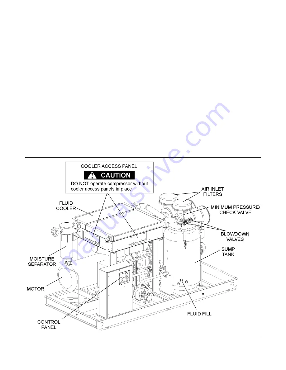
2.2 DESCRIPTION OF COMPONENTS
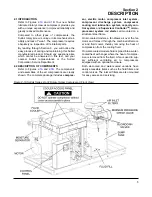
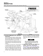
. The components
and assemblies of the air compressors are clearly
shown. The complete package includes
compres-
sor, electric motor, compressor inlet system,
compressor discharge system, compressor
cooling and lubrication system, capacity con-
trol system
and
Supervisor Controller
TM
, micro-
processor system
and
starter
all mounted on a
structural steel frame.
On air-cooled models, a fan draws air over the fan
motor and forces it through the combined aftercool-
er and fluid cooler, thereby removing the heat of
compression from the cooling fluid.
On water-cooled models, fluid is piped into a water-
cooled heat exchanger where the heat of compres-
sion is removed from the fluid. A fan is used to sup-
ply sufficient ventilating air to compressors
equipped with an optional enclosure.
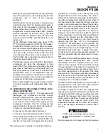
Both air-cooled and water-cooled versions have
easily accessible items such as the fluid filters and
control valves. The inlet air filters are also mounted
for easy access and servicing.
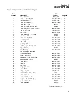
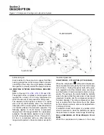
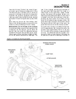
Figure 2-1A Sullair Series LS-32 Rotary Screw Compressor (Front View)
Содержание LS-32
Страница 6: ...NOTES...
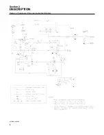
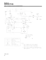
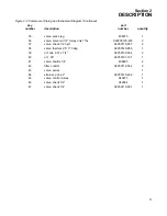
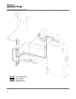
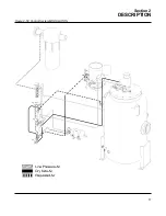
Страница 14: ...Section 2 DESCRIPTION 8 Figure 2 2 Compressor Piping and Instrument Diagram 02250140 998R02...
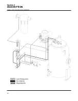
Страница 16: ...Section 2 DESCRIPTION 10 Figure 2 2 Compressor Piping and Instrument Diagram 02250140 998R02...
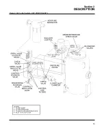
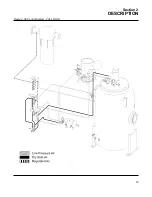
Страница 21: ...Section 2 DESCRIPTION 15 Figure 2 5A Control System KEY COMPONENTS...
Страница 22: ...Section 2 DESCRIPTION 16 Figure 2 5B Control System START...
Страница 23: ...Section 2 DESCRIPTION 17 Figure 2 5C Control System MODULATION...
Страница 24: ...Section 2 DESCRIPTION 18 Figure 2 5D Control System UNLOAD...
Страница 25: ...Section 2 DESCRIPTION 19 Figure 2 5E Control System FULL LOAD...
Страница 28: ...Section 3 SPECIFICATIONS 22 Figure 3 2 Identification LS 32 Air cooled 02250140 997R01...
Страница 32: ...Section 5 SUPERVISOR CONTROLLER 26 Figure 5 1 Supervisor Control Panel...
Страница 44: ...38 NOTES...
Страница 56: ...50 NOTES...
Страница 59: ...53 NOTES...
Страница 60: ...Section 8 ILLUSTRATIONS AND PARTS LIST 54 8 3 MOTOR COMPRESSOR FRAME AND PARTS 02250140 989R01...
Страница 62: ...Section 8 ILLUSTRATIONS AND PARTS LIST 56 8 3 MOTOR COMPRESSOR FRAME AND PARTS 02250140 989R01...
Страница 64: ...Section 8 ILLUSTRATIONS AND PARTS LIST 58 8 4 AIR INLET SYSTEM 02250140 990R02...
Страница 66: ...Section 8 ILLUSTRATIONS AND PARTS LIST 60 8 4 AIR INLET SYSTEM 02250140 990R02...
Страница 68: ...Section 8 ILLUSTRATIONS AND PARTS LIST 62 8 5 FLUID COOLING SYSTEM AIR COOLED 02250140 994R00...
Страница 70: ...Section 8 ILLUSTRATIONS AND PARTS LIST 64 8 5 FLUID COOLING SYSTEM AIR COOLED 02250140 994R00...
Страница 72: ...Section 8 ILLUSTRATIONS AND PARTS LIST 66 8 6 AIR PIPING SYSTEM AIR COOLED 02250140 992R01...
Страница 74: ...Section 8 ILLUSTRATIONS AND PARTS LIST 68 8 6 AIR PIPING SYSTEM AIR COOLED 02250140 992R01...
Страница 76: ...Section 8 ILLUSTRATIONS AND PARTS LIST 70 02250140 993R01 8 7 FLUID PIPING SYSTEM AIR COOLER...
Страница 78: ...Section 8 ILLUSTRATIONS AND PARTS LIST 72 02250140 993R01 8 7 FLUID PIPING SYSTEM AIR COOLER...
Страница 80: ...Section 8 ILLUSTRATIONS AND PARTS LIST 74 02250140 991R00 8 8 SUMP AND PARTS...
Страница 82: ...Section 8 ILLUSTRATIONS AND PARTS LIST 76 02250140 991R00 8 8 SUMP AND PARTS...
Страница 84: ...Section 8 ILLUSTRATIONS AND PARTS LIST 78 8 9 SULLICON CONTROL 02250134 158R00...
Страница 86: ...Section 8 ILLUSTRATIONS AND PARTS LIST 80 8 10 COMPRESSOR ACTUATOR...
Страница 88: ...Section 8 ILLUSTRATIONS AND PARTS LIST 82 8 11 PNEUMATIC CONTROLS 02250140 996R00...
Страница 90: ...Section 8 ILLUSTRATIONS AND PARTS LIST 84 8 11 PNEUMATIC CONTROLS 02250140 996R00...
Страница 92: ...Section 8 ILLUSTRATIONS AND PARTS LIST 86 8 11 PNEUMATIC CONTROLS 02250140 996R00...
Страница 94: ...Section 8 ILLUSTRATIONS AND PARTS LIST 88 8 12 CONTROL BOX SOLID STATE 02250122 005R04...
Страница 96: ...Section 8 ILLUSTRATIONS AND PARTS LIST 90 8 13 CONTROL BOX FULL VOLTAGE 02250122 511R04...
Страница 98: ...Section 8 ILLUSTRATIONS AND PARTS LIST 92 8 14 CONTROL BOX WYE DELTA 02250122 516R08...
Страница 100: ...Section 8 ILLUSTRATIONS AND PARTS LIST 94 8 15 ENCLOSURE AIR COOLED 02250140 995R00...
Страница 102: ...Section 8 ILLUSTRATIONS AND PARTS LIST 96 8 15 ENCLOSURE AIR COOLED 02250140 995R00...
Страница 104: ...Section 8 ILLUSTRATIONS AND PARTS LIST 98 8 16 DECAL GROUP...
Страница 106: ...Section 8 ILLUSTRATIONS AND PARTS LIST 100 8 16 DECAL GROUP...
Страница 108: ...Section 8 ILLUSTRATIONS AND PARTS LIST 102 8 16 DECAL GROUP...
Страница 110: ...Section 8 ILLUSTRATIONS AND PARTS LIST 104 8 17 DECAL LOCATIONS...
Страница 112: ...Section 8 ILLUSTRATIONS AND PARTS LIST 106 8 18 DECAL LOCATIONS ENCLOSURE...
Страница 114: ...Section 8 ILLUSTRATIONS AND PARTS LIST 108 8 19 DECAL LOCATIONS CONTROL BOX...
Страница 116: ...Section 8 ILLUSTRATIONS AND PARTS LIST 110 02250140 999R00 8 20 WIRING DIAGRAM AIR COOLED CUSTOMER SUPPLIED STARTER...
Страница 117: ...111 NOTES...


