Section 2
DESCRIPTION
7
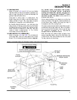
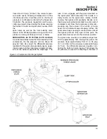
fluid flow by forcing the fluid from the high pressure
area of the sump to an area of lower pressure in the
compressor unit. In case of low pressure
machines
*
.
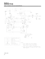
Fluid flows from the receiver/sump to strainer, pump
and the thermal valve. The thermal valve bypass is
fully open to the compressor unit when the dis-
charge temperature is below 170°F (77°C) for all
compressors, except water-cooled 24KT models,
which is fully open up to 195°F (91°C). The fluid
passes through the thermal valve, the fluid stop
valve, the main fluid filter and directly to the com-
pressor unit.
As the discharge temperature rises above 170°F
(77°C) for all compressors (195°F [91°C] for water-
cooled 24KT models), due to the heat of compres-
sion, the thermal valve bypass begins to close and
a portion of the fluid then flows through the cooler.
From the cooler, the fluid flows to the fluid stop
valve, the main filter, and on to the compressor unit.
The fluid filter has a replacement element and an
integral pressure bypass valve.
The fluid stop valve prevents fluid from flooding the
compressor unit when the compressor is shut
down. When the compressor is operating, the fluid
stop valve is held open by air pressure from the
fluid pump allowing a free flow of fluid from the
receiver/sump back to the compressor unit. On
shutdown, the compressor unit pressure is reduced,
causing the fluid stop valve to close and isolate the
compressor unit from the cooling system.
Water-cooled models have a water pressure switch
to prevent operation with inadequate water pres-
sure.
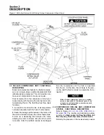
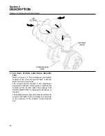
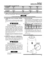
2.5 COMPRESSOR DISCHARGE SYSTEM, FUNC-
TIONAL DESCRIPTION
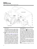
. The compressor unit
discharges the compressed air/fluid mixture
through a discharge check valve into the combina-
tion receiver/sump. The discharge check valve pre-
vents air/fluid in the receiver from returning to the
compression chamber after the compressor has
been shut down. The receiver has three functions:
1.
It acts as a primary fluid separator.
2.
It serves as the compressor fluid sump.
3.
It houses the final fluid/air separator elements.
The compressed air/fluid mixture enters the receiv-
er and is directed against an internal baffle. The
direction of movement is changed and its velocity
significantly reduced, thus causing the large
droplets of fluid to fall to the bottom of the receiv-
er/sump. The fractional percentage of fluid remain-
ing in the compressed air collects on the surface of
the nested separator elements (primary and sec-
ondary) as the compressed air flows through them.
Two return lines (or scavenge tubes) lead from the
bottom of each separator element to the low pres-
sure inlet region of the compressor unit. Fluid col-
lecting on the bottom of each separator is returned
to the compressor due to the pressure difference
between the receiver and the compressor inlet.
Sight glasses are located in the return lines to
observe this fluid flow. dP1 on the Supervisor
Controller
TM
microprocessor control monitors the
condition of the separator elements by reading the
differential pressure on the digital display. At a dif-
ferential of 10 psig (0.7 bar), or greater, the opera-
tor will be told to service the separator elements. At
this time, separator element replacement is neces-
sary.
The receiver is an ASME pressure vessel. A combi-
nation minimum pressure/check valve, located
downstream from the separator, assures a mini-
mum receiver pressure of 40 psig (2.8 bar) during
full load operation. This pressure is necessary for
proper air/fluid separation and proper fluid circula-
tion while supplying air to the system. This valve
also acts as a check valve preventing compressed
air in the service line from bleeding back into the
receiver on shutdown and during operation of the
compressor in an unloaded condition.
A pressure relief valve (located on the wet side of
the separator) is set to open if the sump pressure
exceeds the rated pressure of the tank.
All Sullair compressor models are equipped with
high pressure shutdown protection to shut down the
compressor at 20-35 psi above rated pressure. This
prevents the pressure relief valve from opening
under normal conditions, thereby preventing fluid
loss through the pressure relief valve. The
Supervisor Controller will shut down the compres-
sor if the discharge temperature reaches 235°F
(113°C).
DO NOT remove caps, plugs, and/or other com-
ponents when compressor is running or pres-
surized.
Stop compressor and relieve all internal pressure
*
An external pump is provided to assist the fluid flow.
Содержание LS-32
Страница 6: ...NOTES...
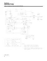
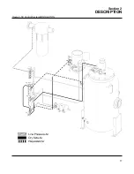
Страница 14: ...Section 2 DESCRIPTION 8 Figure 2 2 Compressor Piping and Instrument Diagram 02250140 998R02...
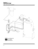
Страница 16: ...Section 2 DESCRIPTION 10 Figure 2 2 Compressor Piping and Instrument Diagram 02250140 998R02...
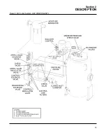
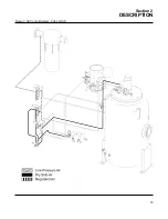
Страница 21: ...Section 2 DESCRIPTION 15 Figure 2 5A Control System KEY COMPONENTS...
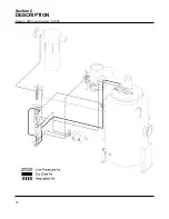
Страница 22: ...Section 2 DESCRIPTION 16 Figure 2 5B Control System START...
Страница 23: ...Section 2 DESCRIPTION 17 Figure 2 5C Control System MODULATION...
Страница 24: ...Section 2 DESCRIPTION 18 Figure 2 5D Control System UNLOAD...
Страница 25: ...Section 2 DESCRIPTION 19 Figure 2 5E Control System FULL LOAD...
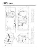
Страница 28: ...Section 3 SPECIFICATIONS 22 Figure 3 2 Identification LS 32 Air cooled 02250140 997R01...
Страница 32: ...Section 5 SUPERVISOR CONTROLLER 26 Figure 5 1 Supervisor Control Panel...
Страница 44: ...38 NOTES...
Страница 56: ...50 NOTES...
Страница 59: ...53 NOTES...
Страница 60: ...Section 8 ILLUSTRATIONS AND PARTS LIST 54 8 3 MOTOR COMPRESSOR FRAME AND PARTS 02250140 989R01...
Страница 62: ...Section 8 ILLUSTRATIONS AND PARTS LIST 56 8 3 MOTOR COMPRESSOR FRAME AND PARTS 02250140 989R01...
Страница 64: ...Section 8 ILLUSTRATIONS AND PARTS LIST 58 8 4 AIR INLET SYSTEM 02250140 990R02...
Страница 66: ...Section 8 ILLUSTRATIONS AND PARTS LIST 60 8 4 AIR INLET SYSTEM 02250140 990R02...
Страница 68: ...Section 8 ILLUSTRATIONS AND PARTS LIST 62 8 5 FLUID COOLING SYSTEM AIR COOLED 02250140 994R00...
Страница 70: ...Section 8 ILLUSTRATIONS AND PARTS LIST 64 8 5 FLUID COOLING SYSTEM AIR COOLED 02250140 994R00...
Страница 72: ...Section 8 ILLUSTRATIONS AND PARTS LIST 66 8 6 AIR PIPING SYSTEM AIR COOLED 02250140 992R01...
Страница 74: ...Section 8 ILLUSTRATIONS AND PARTS LIST 68 8 6 AIR PIPING SYSTEM AIR COOLED 02250140 992R01...
Страница 76: ...Section 8 ILLUSTRATIONS AND PARTS LIST 70 02250140 993R01 8 7 FLUID PIPING SYSTEM AIR COOLER...
Страница 78: ...Section 8 ILLUSTRATIONS AND PARTS LIST 72 02250140 993R01 8 7 FLUID PIPING SYSTEM AIR COOLER...
Страница 80: ...Section 8 ILLUSTRATIONS AND PARTS LIST 74 02250140 991R00 8 8 SUMP AND PARTS...
Страница 82: ...Section 8 ILLUSTRATIONS AND PARTS LIST 76 02250140 991R00 8 8 SUMP AND PARTS...
Страница 84: ...Section 8 ILLUSTRATIONS AND PARTS LIST 78 8 9 SULLICON CONTROL 02250134 158R00...
Страница 86: ...Section 8 ILLUSTRATIONS AND PARTS LIST 80 8 10 COMPRESSOR ACTUATOR...
Страница 88: ...Section 8 ILLUSTRATIONS AND PARTS LIST 82 8 11 PNEUMATIC CONTROLS 02250140 996R00...
Страница 90: ...Section 8 ILLUSTRATIONS AND PARTS LIST 84 8 11 PNEUMATIC CONTROLS 02250140 996R00...
Страница 92: ...Section 8 ILLUSTRATIONS AND PARTS LIST 86 8 11 PNEUMATIC CONTROLS 02250140 996R00...
Страница 94: ...Section 8 ILLUSTRATIONS AND PARTS LIST 88 8 12 CONTROL BOX SOLID STATE 02250122 005R04...
Страница 96: ...Section 8 ILLUSTRATIONS AND PARTS LIST 90 8 13 CONTROL BOX FULL VOLTAGE 02250122 511R04...
Страница 98: ...Section 8 ILLUSTRATIONS AND PARTS LIST 92 8 14 CONTROL BOX WYE DELTA 02250122 516R08...
Страница 100: ...Section 8 ILLUSTRATIONS AND PARTS LIST 94 8 15 ENCLOSURE AIR COOLED 02250140 995R00...
Страница 102: ...Section 8 ILLUSTRATIONS AND PARTS LIST 96 8 15 ENCLOSURE AIR COOLED 02250140 995R00...
Страница 104: ...Section 8 ILLUSTRATIONS AND PARTS LIST 98 8 16 DECAL GROUP...
Страница 106: ...Section 8 ILLUSTRATIONS AND PARTS LIST 100 8 16 DECAL GROUP...
Страница 108: ...Section 8 ILLUSTRATIONS AND PARTS LIST 102 8 16 DECAL GROUP...
Страница 110: ...Section 8 ILLUSTRATIONS AND PARTS LIST 104 8 17 DECAL LOCATIONS...
Страница 112: ...Section 8 ILLUSTRATIONS AND PARTS LIST 106 8 18 DECAL LOCATIONS ENCLOSURE...
Страница 114: ...Section 8 ILLUSTRATIONS AND PARTS LIST 108 8 19 DECAL LOCATIONS CONTROL BOX...
Страница 116: ...Section 8 ILLUSTRATIONS AND PARTS LIST 110 02250140 999R00 8 20 WIRING DIAGRAM AIR COOLED CUSTOMER SUPPLIED STARTER...
Страница 117: ...111 NOTES...


