Section 2
DESCRIPTION
6
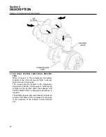
2.3 SULLAIR COMPRESSOR UNIT, FUNCTIONAL
DESCRIPTION
Sullair air compressors feature the Sullair compres-
sor unit, a single-stage, positive displacement fluid
lubricated-type compressor. This unit provides con-
tinuous air compression to meet your needs.
Fluid is injected into the compressor unit where it
mixes directly with the air as the internal rotors turn,
compressing the air. The fluid flow has three basic
functions:
1.
As coolant, it controls the rise of air temperature
normally associated with the heat of compression.
2.
Seals the leakage paths between the rotors and
the stator and also between the rotors themselves.
3.
Acts as a lubricating film between the rotors
allowing one rotor to directly drive the other, which
is an idler. After the air/fluid mixture is discharged
from the compressor unit, the fluid is separated
from the air. At this time, the air flows to the serv-
ice line and the fluid is cooled in preparation for re-
injection.
With a Sullair compressor, there is no mainte-
nance or inspection of the internal parts of the
compressor unit permitted in accordance with
the terms of the warranty.
2.4 COMPRESSOR COOLING AND LUBRICATION
SYSTEM, FUNCTIONAL DESCRIPTION
. The cooling and lubrication system
consists of a
fluid cooler, full flow fluid filter, full
flow oil pump, fluid stop valve, thermal valve
.
Normally the pressure in the receiver/sump causes
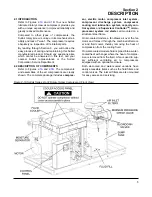
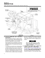
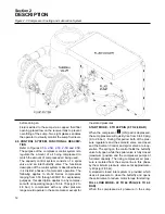
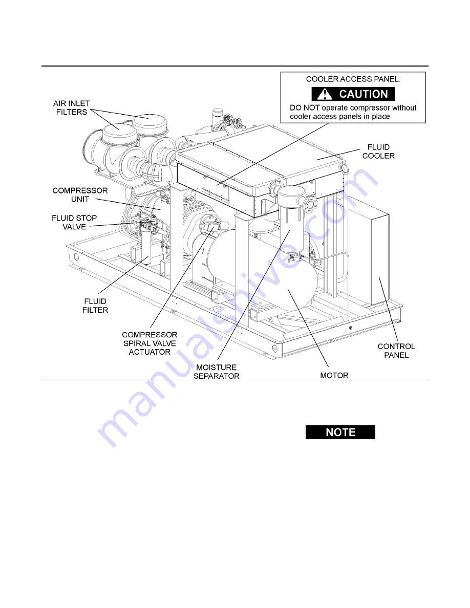
Figure 2-1B Sullair Series LS-32 Rotary Screw Compressor (Rear View)
Содержание LS-32
Страница 6: ...NOTES...
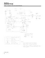
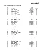
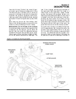
Страница 14: ...Section 2 DESCRIPTION 8 Figure 2 2 Compressor Piping and Instrument Diagram 02250140 998R02...
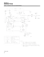
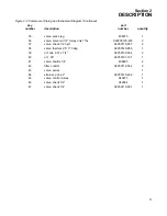
Страница 16: ...Section 2 DESCRIPTION 10 Figure 2 2 Compressor Piping and Instrument Diagram 02250140 998R02...
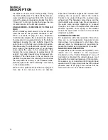
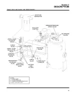
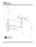
Страница 21: ...Section 2 DESCRIPTION 15 Figure 2 5A Control System KEY COMPONENTS...
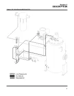
Страница 22: ...Section 2 DESCRIPTION 16 Figure 2 5B Control System START...
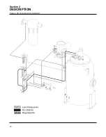
Страница 23: ...Section 2 DESCRIPTION 17 Figure 2 5C Control System MODULATION...
Страница 24: ...Section 2 DESCRIPTION 18 Figure 2 5D Control System UNLOAD...
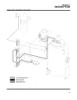
Страница 25: ...Section 2 DESCRIPTION 19 Figure 2 5E Control System FULL LOAD...
Страница 28: ...Section 3 SPECIFICATIONS 22 Figure 3 2 Identification LS 32 Air cooled 02250140 997R01...
Страница 32: ...Section 5 SUPERVISOR CONTROLLER 26 Figure 5 1 Supervisor Control Panel...
Страница 44: ...38 NOTES...
Страница 56: ...50 NOTES...
Страница 59: ...53 NOTES...
Страница 60: ...Section 8 ILLUSTRATIONS AND PARTS LIST 54 8 3 MOTOR COMPRESSOR FRAME AND PARTS 02250140 989R01...
Страница 62: ...Section 8 ILLUSTRATIONS AND PARTS LIST 56 8 3 MOTOR COMPRESSOR FRAME AND PARTS 02250140 989R01...
Страница 64: ...Section 8 ILLUSTRATIONS AND PARTS LIST 58 8 4 AIR INLET SYSTEM 02250140 990R02...
Страница 66: ...Section 8 ILLUSTRATIONS AND PARTS LIST 60 8 4 AIR INLET SYSTEM 02250140 990R02...
Страница 68: ...Section 8 ILLUSTRATIONS AND PARTS LIST 62 8 5 FLUID COOLING SYSTEM AIR COOLED 02250140 994R00...
Страница 70: ...Section 8 ILLUSTRATIONS AND PARTS LIST 64 8 5 FLUID COOLING SYSTEM AIR COOLED 02250140 994R00...
Страница 72: ...Section 8 ILLUSTRATIONS AND PARTS LIST 66 8 6 AIR PIPING SYSTEM AIR COOLED 02250140 992R01...
Страница 74: ...Section 8 ILLUSTRATIONS AND PARTS LIST 68 8 6 AIR PIPING SYSTEM AIR COOLED 02250140 992R01...
Страница 76: ...Section 8 ILLUSTRATIONS AND PARTS LIST 70 02250140 993R01 8 7 FLUID PIPING SYSTEM AIR COOLER...
Страница 78: ...Section 8 ILLUSTRATIONS AND PARTS LIST 72 02250140 993R01 8 7 FLUID PIPING SYSTEM AIR COOLER...
Страница 80: ...Section 8 ILLUSTRATIONS AND PARTS LIST 74 02250140 991R00 8 8 SUMP AND PARTS...
Страница 82: ...Section 8 ILLUSTRATIONS AND PARTS LIST 76 02250140 991R00 8 8 SUMP AND PARTS...
Страница 84: ...Section 8 ILLUSTRATIONS AND PARTS LIST 78 8 9 SULLICON CONTROL 02250134 158R00...
Страница 86: ...Section 8 ILLUSTRATIONS AND PARTS LIST 80 8 10 COMPRESSOR ACTUATOR...
Страница 88: ...Section 8 ILLUSTRATIONS AND PARTS LIST 82 8 11 PNEUMATIC CONTROLS 02250140 996R00...
Страница 90: ...Section 8 ILLUSTRATIONS AND PARTS LIST 84 8 11 PNEUMATIC CONTROLS 02250140 996R00...
Страница 92: ...Section 8 ILLUSTRATIONS AND PARTS LIST 86 8 11 PNEUMATIC CONTROLS 02250140 996R00...
Страница 94: ...Section 8 ILLUSTRATIONS AND PARTS LIST 88 8 12 CONTROL BOX SOLID STATE 02250122 005R04...
Страница 96: ...Section 8 ILLUSTRATIONS AND PARTS LIST 90 8 13 CONTROL BOX FULL VOLTAGE 02250122 511R04...
Страница 98: ...Section 8 ILLUSTRATIONS AND PARTS LIST 92 8 14 CONTROL BOX WYE DELTA 02250122 516R08...
Страница 100: ...Section 8 ILLUSTRATIONS AND PARTS LIST 94 8 15 ENCLOSURE AIR COOLED 02250140 995R00...
Страница 102: ...Section 8 ILLUSTRATIONS AND PARTS LIST 96 8 15 ENCLOSURE AIR COOLED 02250140 995R00...
Страница 104: ...Section 8 ILLUSTRATIONS AND PARTS LIST 98 8 16 DECAL GROUP...
Страница 106: ...Section 8 ILLUSTRATIONS AND PARTS LIST 100 8 16 DECAL GROUP...
Страница 108: ...Section 8 ILLUSTRATIONS AND PARTS LIST 102 8 16 DECAL GROUP...
Страница 110: ...Section 8 ILLUSTRATIONS AND PARTS LIST 104 8 17 DECAL LOCATIONS...
Страница 112: ...Section 8 ILLUSTRATIONS AND PARTS LIST 106 8 18 DECAL LOCATIONS ENCLOSURE...
Страница 114: ...Section 8 ILLUSTRATIONS AND PARTS LIST 108 8 19 DECAL LOCATIONS CONTROL BOX...
Страница 116: ...Section 8 ILLUSTRATIONS AND PARTS LIST 110 02250140 999R00 8 20 WIRING DIAGRAM AIR COOLED CUSTOMER SUPPLIED STARTER...
Страница 117: ...111 NOTES...


