Section 5
SUPERVISOR
27
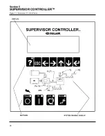
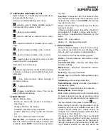
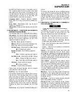
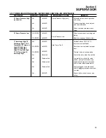
5.1 SUPERVISOR KEYBOARD LAYOUT
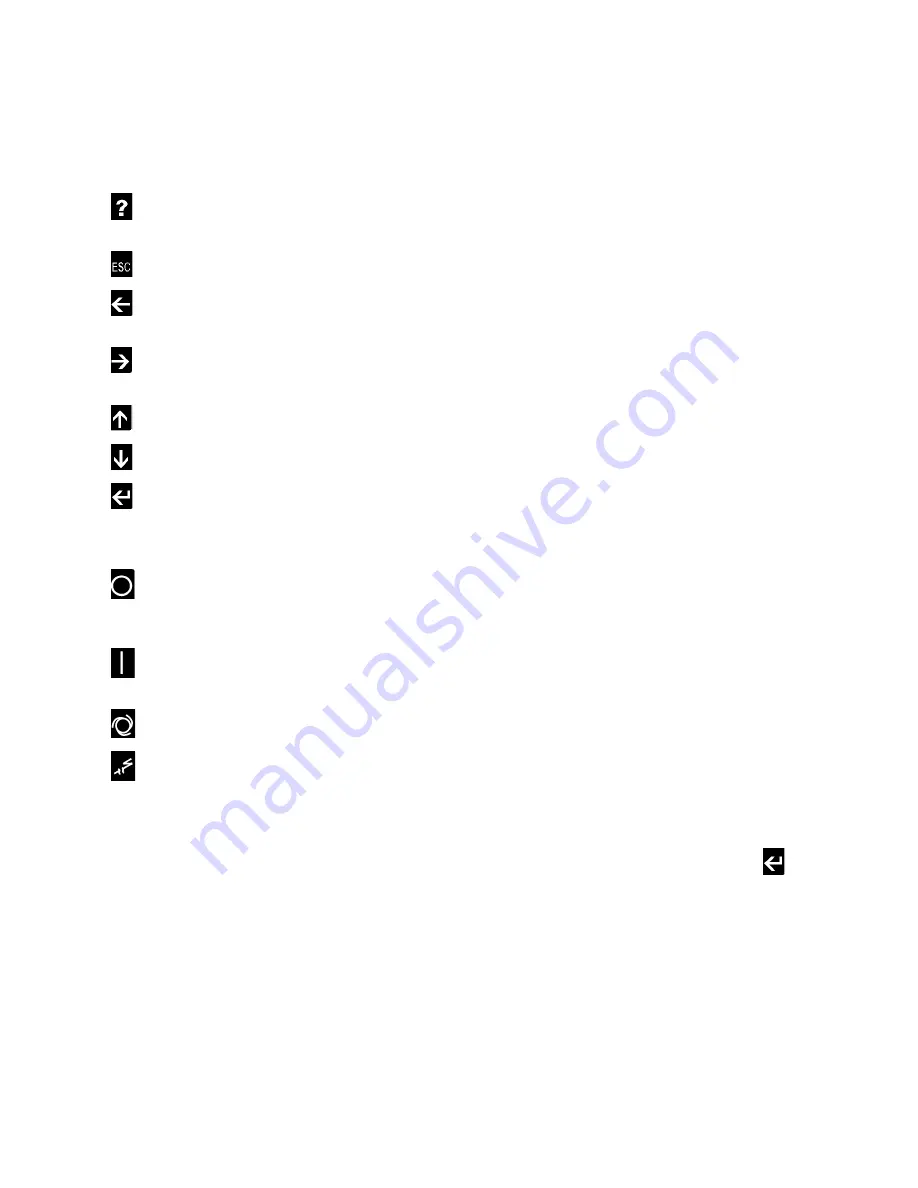
. The Display module has eleven
keys grouped in two rows.
The top row has the following seven keys :
-
Help key, used to display possible causes of
and correction for an alarm or fault.
-
Returns to main display.
-Used to edit text or numbers (move cursor
left).
-
Used to edit text or numbers (move cursor
right).
-
Used to change numbers or text, or scroll.
-
Used to change numbers or text, or scroll.
-
Used to select an item from a menu, or start
and end an edit on a parameter
The bottom row has four keys :
-
Stop, stops machine. Clears fault and warning
if machine is stopped, and conditions have been
eliminated.
-
Run, starts machine. Clears warnings if
machine is running.
-
Toggles auto mode.
-
Toggles Local/Remote mode. This can be
used to disable sequencing.
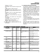
5.2 MAIN DISPLAY
Line 1 -
Machine state :
E-Stop - E- Stop button pressed, or auxiliary e-
stop present.
Stopped - Machine not running.
Unloaded - Machine running unloaded.
Loaded - Machine running, loaded and modulat-
ing.
Full Load - Machine forced to full load.
Remote Stop -
Compressor is off but armed to
start. The machine will start when the remote start
contact is closed.
NOTE :
the machine may start at
any time.
Seq Stop -
Compressor is off but armed to start.
The machine will start when the sequencing condi-
tions meet the criteria to start.
NOTE:
the machine
may start at any time.
Line 2 -
Fault or Warning, blank means no fault or
warning is present.
If there are multiple alarms, they will be shown for 2
seconds each. If an alarm is active, pressing the ‘?’
key will give troubleshooting information on that
alarm.
Line 3 -
P2 - Line pressure
Line 4 -
T1 - Discharge Temperature
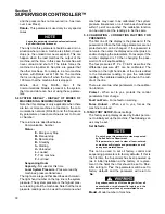
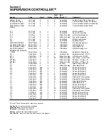
5.3 FUNCTION MENU
While in the main display, if any of the arrow keys
are pressed, the function menu is displayed. This
menu is used to view status or edit parameters.
The function menu has the following entries :
Status -
Current pressures, temperatures, inputs
and outputs.
Control Parameters -
Pressure and temperature
and timer settings.
Maintenance -
Preventive maintenance informa-
tion and timers.
Fault Log -
Log of previous faults.
Sensor Log -
Log of sensor readings leading up to
a fault.
Sequencing -
Sequencing parameters.
System Display -
Display of modes of machines in
a sequencing system.
Calibration -
Correction factors for pressures.
Factory Setup -
Model settings.
Test -
Used by Sullair personnel for troubleshooting
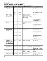
To select a function, use the up and down arrow
keys to scroll to the desired function as indicated on
last line of display, then press the enter
key.
After entering a function, the information can be
viewed by using the up and down arrow keys. If the
function shows status then values cannot be
changed. If the function displays parameters, then
the values can be changed.
To change a value, scroll to the line to be changed
using the up arrow and down arrow keys, and push
the enter button. The value can be changed by
using the up arrow or down arrow keys. When edit-
ing is finished, pushing the enter key will fix the
Содержание LS-32
Страница 6: ...NOTES...
Страница 14: ...Section 2 DESCRIPTION 8 Figure 2 2 Compressor Piping and Instrument Diagram 02250140 998R02...
Страница 16: ...Section 2 DESCRIPTION 10 Figure 2 2 Compressor Piping and Instrument Diagram 02250140 998R02...
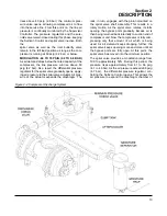
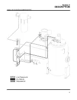
Страница 21: ...Section 2 DESCRIPTION 15 Figure 2 5A Control System KEY COMPONENTS...
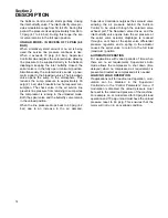
Страница 22: ...Section 2 DESCRIPTION 16 Figure 2 5B Control System START...
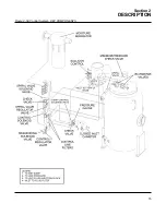
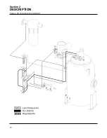
Страница 23: ...Section 2 DESCRIPTION 17 Figure 2 5C Control System MODULATION...
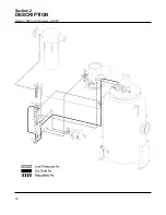
Страница 24: ...Section 2 DESCRIPTION 18 Figure 2 5D Control System UNLOAD...
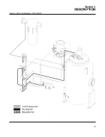
Страница 25: ...Section 2 DESCRIPTION 19 Figure 2 5E Control System FULL LOAD...
Страница 28: ...Section 3 SPECIFICATIONS 22 Figure 3 2 Identification LS 32 Air cooled 02250140 997R01...
Страница 32: ...Section 5 SUPERVISOR CONTROLLER 26 Figure 5 1 Supervisor Control Panel...
Страница 44: ...38 NOTES...
Страница 56: ...50 NOTES...
Страница 59: ...53 NOTES...
Страница 60: ...Section 8 ILLUSTRATIONS AND PARTS LIST 54 8 3 MOTOR COMPRESSOR FRAME AND PARTS 02250140 989R01...
Страница 62: ...Section 8 ILLUSTRATIONS AND PARTS LIST 56 8 3 MOTOR COMPRESSOR FRAME AND PARTS 02250140 989R01...
Страница 64: ...Section 8 ILLUSTRATIONS AND PARTS LIST 58 8 4 AIR INLET SYSTEM 02250140 990R02...
Страница 66: ...Section 8 ILLUSTRATIONS AND PARTS LIST 60 8 4 AIR INLET SYSTEM 02250140 990R02...
Страница 68: ...Section 8 ILLUSTRATIONS AND PARTS LIST 62 8 5 FLUID COOLING SYSTEM AIR COOLED 02250140 994R00...
Страница 70: ...Section 8 ILLUSTRATIONS AND PARTS LIST 64 8 5 FLUID COOLING SYSTEM AIR COOLED 02250140 994R00...
Страница 72: ...Section 8 ILLUSTRATIONS AND PARTS LIST 66 8 6 AIR PIPING SYSTEM AIR COOLED 02250140 992R01...
Страница 74: ...Section 8 ILLUSTRATIONS AND PARTS LIST 68 8 6 AIR PIPING SYSTEM AIR COOLED 02250140 992R01...
Страница 76: ...Section 8 ILLUSTRATIONS AND PARTS LIST 70 02250140 993R01 8 7 FLUID PIPING SYSTEM AIR COOLER...
Страница 78: ...Section 8 ILLUSTRATIONS AND PARTS LIST 72 02250140 993R01 8 7 FLUID PIPING SYSTEM AIR COOLER...
Страница 80: ...Section 8 ILLUSTRATIONS AND PARTS LIST 74 02250140 991R00 8 8 SUMP AND PARTS...
Страница 82: ...Section 8 ILLUSTRATIONS AND PARTS LIST 76 02250140 991R00 8 8 SUMP AND PARTS...
Страница 84: ...Section 8 ILLUSTRATIONS AND PARTS LIST 78 8 9 SULLICON CONTROL 02250134 158R00...
Страница 86: ...Section 8 ILLUSTRATIONS AND PARTS LIST 80 8 10 COMPRESSOR ACTUATOR...
Страница 88: ...Section 8 ILLUSTRATIONS AND PARTS LIST 82 8 11 PNEUMATIC CONTROLS 02250140 996R00...
Страница 90: ...Section 8 ILLUSTRATIONS AND PARTS LIST 84 8 11 PNEUMATIC CONTROLS 02250140 996R00...
Страница 92: ...Section 8 ILLUSTRATIONS AND PARTS LIST 86 8 11 PNEUMATIC CONTROLS 02250140 996R00...
Страница 94: ...Section 8 ILLUSTRATIONS AND PARTS LIST 88 8 12 CONTROL BOX SOLID STATE 02250122 005R04...
Страница 96: ...Section 8 ILLUSTRATIONS AND PARTS LIST 90 8 13 CONTROL BOX FULL VOLTAGE 02250122 511R04...
Страница 98: ...Section 8 ILLUSTRATIONS AND PARTS LIST 92 8 14 CONTROL BOX WYE DELTA 02250122 516R08...
Страница 100: ...Section 8 ILLUSTRATIONS AND PARTS LIST 94 8 15 ENCLOSURE AIR COOLED 02250140 995R00...
Страница 102: ...Section 8 ILLUSTRATIONS AND PARTS LIST 96 8 15 ENCLOSURE AIR COOLED 02250140 995R00...
Страница 104: ...Section 8 ILLUSTRATIONS AND PARTS LIST 98 8 16 DECAL GROUP...
Страница 106: ...Section 8 ILLUSTRATIONS AND PARTS LIST 100 8 16 DECAL GROUP...
Страница 108: ...Section 8 ILLUSTRATIONS AND PARTS LIST 102 8 16 DECAL GROUP...
Страница 110: ...Section 8 ILLUSTRATIONS AND PARTS LIST 104 8 17 DECAL LOCATIONS...
Страница 112: ...Section 8 ILLUSTRATIONS AND PARTS LIST 106 8 18 DECAL LOCATIONS ENCLOSURE...
Страница 114: ...Section 8 ILLUSTRATIONS AND PARTS LIST 108 8 19 DECAL LOCATIONS CONTROL BOX...
Страница 116: ...Section 8 ILLUSTRATIONS AND PARTS LIST 110 02250140 999R00 8 20 WIRING DIAGRAM AIR COOLED CUSTOMER SUPPLIED STARTER...
Страница 117: ...111 NOTES...

