Section 5
SUPERVISOR CONTROLLER™
30
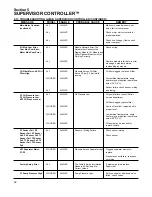
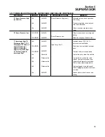
and the pressure has not recovered (i.e. has risen
over ‘Low Press’).
Rotate -
This parameter is used only in very special
cases.
Leave this parameter disabled unless instructed
by Sullair Service Personnel.
The only time this parameter should be used is in a
situation where, once a machine is started, it never
stops (ie. the unload timer never expires). This can
happen when the load matches the output of the
machine, all the time. In this case the machine will
never unload and shut off. The rotate forces the
machine to stop after it’s Seq Hrs. are greater that
the other machines. For example in a two machine
system, with Rotate set at 100 hrs. The machine
that is running will shut off when the Seq Hrs. are
100 more that the machine that is stopped.
Minute, Hour, Day, Month, Year- If the
Communications Module is present in the system,
the time and date can be set using these parame-
ters.
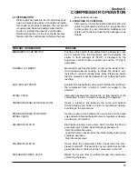
5.8 SYSTEM DISPLAY - DISPLAY OF MODES OF
MACHINES IN A SEQUENCING SYSTEM
Note that this display is only applicable when there
are two or more machines connected to the com-
munications network (RS-485) and the Sequence
By parameters on each machine are set to ‘Hours’
or ‘Number’.
The columns are described below
Communication Number
Status -
E -
Emergency Stop
M -
Manual stop
R -
Remote stop
B -
Standby
S -
Starting
U -
Unloaded
L -
Loaded
T -
Trim machine
F -
Full load
Sequencing Hours
Capacity
- Not used at this time
Local System Pressure
- Pressure read by
machines’ pressure transducer
The top line is a legend that describes each column.
The right hand number on the top line is the system
pressure. The system pressure is the highest pres-
sure reading of all the machines. Note that the local
pressure readings can be used to determine what
machines may need to be calibrated. The system
pressure transducers on all machines should read
within 1 psi of one another. The calibration function
can be used to set the readings to be the same.
5.9 CALIBRATION - CORRECTION FACTORS FOR
PRESSURES
The first line of this display is the password. If the
password is 0 then the following parameters are not
protected and can be changed. If the password is
non-zero, then enter the displayed number plus 4 to
enable changing the parameters. For example if the
number displayed is 10 then changing the pass-
word to 14 will enable editing.
The four pressures P1, P2, P3 & P4 as well as the
differential pressure dP1 can be calibrated. The
number on the right hand side of the line is added
to the transducer reading to give the calibrated
reading. The calibrated reading is shown in the mid-
dle of the line.
There are also two other parameters in the calibra-
tion function :
Protect -
When set to yes, protects the control
parameters from change.
Fault on Warn -
Force fault on warning.
Force Unload -
When set to yes, forces the
machine to unload.
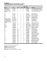
5.10 FACTORY SETUP-
Model settings.
The factory setup display is used by Sullair person-
nel to initially set up the machine. The following val-
ues may be set.
Set Defaults
-
Do not change this parameter unless requested
by Sullair Service Department.
This parameter is used to clear all user-entered
or model-specific inputs and parameters, as well
as any accumulated hours.
This can be used to set all factory, control and
sequencing parameters to factory defaults. If this is
the first time the Supervisor has been powered up
(as in initial installation at the factory, or replace-
ment in the field) then this should be set to ‘
Yes
’.
After setting to ‘
Yes
’ the parameters will be set to
factory defaults and the parameter will return to
‘
No
’.
Any subsequent use of this setting will clear all
user-entered or model-specific inputs and the
parameters as well as any accumulated hours.
Model -
Model number of machine.
Содержание LS-32
Страница 6: ...NOTES...
Страница 14: ...Section 2 DESCRIPTION 8 Figure 2 2 Compressor Piping and Instrument Diagram 02250140 998R02...
Страница 16: ...Section 2 DESCRIPTION 10 Figure 2 2 Compressor Piping and Instrument Diagram 02250140 998R02...
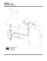
Страница 21: ...Section 2 DESCRIPTION 15 Figure 2 5A Control System KEY COMPONENTS...
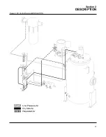
Страница 22: ...Section 2 DESCRIPTION 16 Figure 2 5B Control System START...
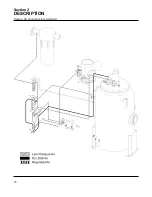
Страница 23: ...Section 2 DESCRIPTION 17 Figure 2 5C Control System MODULATION...
Страница 24: ...Section 2 DESCRIPTION 18 Figure 2 5D Control System UNLOAD...
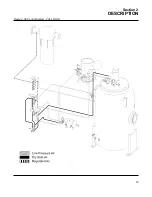
Страница 25: ...Section 2 DESCRIPTION 19 Figure 2 5E Control System FULL LOAD...
Страница 28: ...Section 3 SPECIFICATIONS 22 Figure 3 2 Identification LS 32 Air cooled 02250140 997R01...
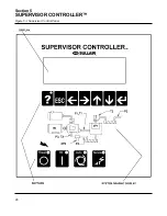
Страница 32: ...Section 5 SUPERVISOR CONTROLLER 26 Figure 5 1 Supervisor Control Panel...
Страница 44: ...38 NOTES...
Страница 56: ...50 NOTES...
Страница 59: ...53 NOTES...
Страница 60: ...Section 8 ILLUSTRATIONS AND PARTS LIST 54 8 3 MOTOR COMPRESSOR FRAME AND PARTS 02250140 989R01...
Страница 62: ...Section 8 ILLUSTRATIONS AND PARTS LIST 56 8 3 MOTOR COMPRESSOR FRAME AND PARTS 02250140 989R01...
Страница 64: ...Section 8 ILLUSTRATIONS AND PARTS LIST 58 8 4 AIR INLET SYSTEM 02250140 990R02...
Страница 66: ...Section 8 ILLUSTRATIONS AND PARTS LIST 60 8 4 AIR INLET SYSTEM 02250140 990R02...
Страница 68: ...Section 8 ILLUSTRATIONS AND PARTS LIST 62 8 5 FLUID COOLING SYSTEM AIR COOLED 02250140 994R00...
Страница 70: ...Section 8 ILLUSTRATIONS AND PARTS LIST 64 8 5 FLUID COOLING SYSTEM AIR COOLED 02250140 994R00...
Страница 72: ...Section 8 ILLUSTRATIONS AND PARTS LIST 66 8 6 AIR PIPING SYSTEM AIR COOLED 02250140 992R01...
Страница 74: ...Section 8 ILLUSTRATIONS AND PARTS LIST 68 8 6 AIR PIPING SYSTEM AIR COOLED 02250140 992R01...
Страница 76: ...Section 8 ILLUSTRATIONS AND PARTS LIST 70 02250140 993R01 8 7 FLUID PIPING SYSTEM AIR COOLER...
Страница 78: ...Section 8 ILLUSTRATIONS AND PARTS LIST 72 02250140 993R01 8 7 FLUID PIPING SYSTEM AIR COOLER...
Страница 80: ...Section 8 ILLUSTRATIONS AND PARTS LIST 74 02250140 991R00 8 8 SUMP AND PARTS...
Страница 82: ...Section 8 ILLUSTRATIONS AND PARTS LIST 76 02250140 991R00 8 8 SUMP AND PARTS...
Страница 84: ...Section 8 ILLUSTRATIONS AND PARTS LIST 78 8 9 SULLICON CONTROL 02250134 158R00...
Страница 86: ...Section 8 ILLUSTRATIONS AND PARTS LIST 80 8 10 COMPRESSOR ACTUATOR...
Страница 88: ...Section 8 ILLUSTRATIONS AND PARTS LIST 82 8 11 PNEUMATIC CONTROLS 02250140 996R00...
Страница 90: ...Section 8 ILLUSTRATIONS AND PARTS LIST 84 8 11 PNEUMATIC CONTROLS 02250140 996R00...
Страница 92: ...Section 8 ILLUSTRATIONS AND PARTS LIST 86 8 11 PNEUMATIC CONTROLS 02250140 996R00...
Страница 94: ...Section 8 ILLUSTRATIONS AND PARTS LIST 88 8 12 CONTROL BOX SOLID STATE 02250122 005R04...
Страница 96: ...Section 8 ILLUSTRATIONS AND PARTS LIST 90 8 13 CONTROL BOX FULL VOLTAGE 02250122 511R04...
Страница 98: ...Section 8 ILLUSTRATIONS AND PARTS LIST 92 8 14 CONTROL BOX WYE DELTA 02250122 516R08...
Страница 100: ...Section 8 ILLUSTRATIONS AND PARTS LIST 94 8 15 ENCLOSURE AIR COOLED 02250140 995R00...
Страница 102: ...Section 8 ILLUSTRATIONS AND PARTS LIST 96 8 15 ENCLOSURE AIR COOLED 02250140 995R00...
Страница 104: ...Section 8 ILLUSTRATIONS AND PARTS LIST 98 8 16 DECAL GROUP...
Страница 106: ...Section 8 ILLUSTRATIONS AND PARTS LIST 100 8 16 DECAL GROUP...
Страница 108: ...Section 8 ILLUSTRATIONS AND PARTS LIST 102 8 16 DECAL GROUP...
Страница 110: ...Section 8 ILLUSTRATIONS AND PARTS LIST 104 8 17 DECAL LOCATIONS...
Страница 112: ...Section 8 ILLUSTRATIONS AND PARTS LIST 106 8 18 DECAL LOCATIONS ENCLOSURE...
Страница 114: ...Section 8 ILLUSTRATIONS AND PARTS LIST 108 8 19 DECAL LOCATIONS CONTROL BOX...
Страница 116: ...Section 8 ILLUSTRATIONS AND PARTS LIST 110 02250140 999R00 8 20 WIRING DIAGRAM AIR COOLED CUSTOMER SUPPLIED STARTER...
Страница 117: ...111 NOTES...

