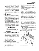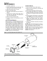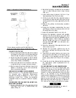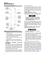
36
Section 6
COMPRESSOR OPERATION
MINIMUM PRESSURE VALVE
PRESSURE RELIEF VALVE
BLOWDOWN VALVE ASSEMBLY
THERMAL MIXING VALVE
FLUID STOP VALVE
SUMP SIGHT GLASSES
SEPARATOR RETURN LINE SIGHT GLASSES
WATER PRESSURE SWITCH
DRAIN VALVES
Maintains 40 psig (2.8 bar) in the receiver tank when the
compressor is running loaded. Also incorporates a check
valve, which prevents compressed air backflow from the sys-
tem when unloaded or shutdown.
Vents the sump vessel to atmosphere before the com-
pressed air pressure exceeds rated tank pressure. Its oper-
ation indicates fault with the Supervisor operation unload
pressure set too high or failure of solenoid valve #1.
Vents the sump vessel to atmosphere during unloading and
shutdown.
Bypasses fluid flow around the cooler until the fluid reaches
a temperature of 170°F, 77°C (195°F for water cooled KT and
≥
150 psi/ 10.3 bar). Useful for fast warm-up during start.
Maintains a minimum temperature during periods of low load
or low ambient temperatures.
Blocks the flow of fluid to the compressor during shutdown,
thus preventing the discharge of fluid through the compres-
sor inlet pipework.
Indicates level of lubricant in the sump. Located on the sump
side, fluid level should be maintained at a level between the
high and low sight glass.
Indicate fluid flow in the separator return lines. Large flow
should be visible during full load operation; little to no flow
during unloaded operation. Sluggish flow during full load
operation indicates the need to clean the strainers fitted to
the return lines.
De-energizes the starter, via the Supervisor, if the
water pressure falls below 10 psig (0.7 bar). This switch is not
adjustable. Used on water-cooled packages only.
Lubricant sump drain valve.
6.3 INITIAL START-UP PROCEDURE
The following procedure should be used to make
the initial start-up of the compressor.
1. Read the preceding pages of this manual thor-
oughly.
2. Jog motor to check for correct rotation of fan
(refer to Section 4.7).
3. Be sure that all preparations and checks
described in the Installation Section have been
made.
4. Open the shut-off valve to the service line.
5. Check for possible leaks in piping.
6. Slowly close the shut-off valve to assure proper
nameplate pressure unload setting is correct.
The compressor will unload at nameplate pres-
sure. If adjustments are necessary, see Control
System Adjustments.
7. Observe the operating temperature. If the oper-
ating temperature exceeds 200°F (93°C) [215°F
(102°C) for water-cooled 24KT and > 150 psi],
CONTROL OR INDICATOR (CONT.)
PURPOSE (CONT.)
Содержание LS-32
Страница 6: ...NOTES...
Страница 14: ...Section 2 DESCRIPTION 8 Figure 2 2 Compressor Piping and Instrument Diagram 02250140 998R02...
Страница 16: ...Section 2 DESCRIPTION 10 Figure 2 2 Compressor Piping and Instrument Diagram 02250140 998R02...
Страница 21: ...Section 2 DESCRIPTION 15 Figure 2 5A Control System KEY COMPONENTS...
Страница 22: ...Section 2 DESCRIPTION 16 Figure 2 5B Control System START...
Страница 23: ...Section 2 DESCRIPTION 17 Figure 2 5C Control System MODULATION...
Страница 24: ...Section 2 DESCRIPTION 18 Figure 2 5D Control System UNLOAD...
Страница 25: ...Section 2 DESCRIPTION 19 Figure 2 5E Control System FULL LOAD...
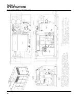
Страница 28: ...Section 3 SPECIFICATIONS 22 Figure 3 2 Identification LS 32 Air cooled 02250140 997R01...
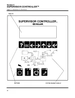
Страница 32: ...Section 5 SUPERVISOR CONTROLLER 26 Figure 5 1 Supervisor Control Panel...
Страница 44: ...38 NOTES...
Страница 56: ...50 NOTES...
Страница 59: ...53 NOTES...
Страница 60: ...Section 8 ILLUSTRATIONS AND PARTS LIST 54 8 3 MOTOR COMPRESSOR FRAME AND PARTS 02250140 989R01...
Страница 62: ...Section 8 ILLUSTRATIONS AND PARTS LIST 56 8 3 MOTOR COMPRESSOR FRAME AND PARTS 02250140 989R01...
Страница 64: ...Section 8 ILLUSTRATIONS AND PARTS LIST 58 8 4 AIR INLET SYSTEM 02250140 990R02...
Страница 66: ...Section 8 ILLUSTRATIONS AND PARTS LIST 60 8 4 AIR INLET SYSTEM 02250140 990R02...
Страница 68: ...Section 8 ILLUSTRATIONS AND PARTS LIST 62 8 5 FLUID COOLING SYSTEM AIR COOLED 02250140 994R00...
Страница 70: ...Section 8 ILLUSTRATIONS AND PARTS LIST 64 8 5 FLUID COOLING SYSTEM AIR COOLED 02250140 994R00...
Страница 72: ...Section 8 ILLUSTRATIONS AND PARTS LIST 66 8 6 AIR PIPING SYSTEM AIR COOLED 02250140 992R01...
Страница 74: ...Section 8 ILLUSTRATIONS AND PARTS LIST 68 8 6 AIR PIPING SYSTEM AIR COOLED 02250140 992R01...
Страница 76: ...Section 8 ILLUSTRATIONS AND PARTS LIST 70 02250140 993R01 8 7 FLUID PIPING SYSTEM AIR COOLER...
Страница 78: ...Section 8 ILLUSTRATIONS AND PARTS LIST 72 02250140 993R01 8 7 FLUID PIPING SYSTEM AIR COOLER...
Страница 80: ...Section 8 ILLUSTRATIONS AND PARTS LIST 74 02250140 991R00 8 8 SUMP AND PARTS...
Страница 82: ...Section 8 ILLUSTRATIONS AND PARTS LIST 76 02250140 991R00 8 8 SUMP AND PARTS...
Страница 84: ...Section 8 ILLUSTRATIONS AND PARTS LIST 78 8 9 SULLICON CONTROL 02250134 158R00...
Страница 86: ...Section 8 ILLUSTRATIONS AND PARTS LIST 80 8 10 COMPRESSOR ACTUATOR...
Страница 88: ...Section 8 ILLUSTRATIONS AND PARTS LIST 82 8 11 PNEUMATIC CONTROLS 02250140 996R00...
Страница 90: ...Section 8 ILLUSTRATIONS AND PARTS LIST 84 8 11 PNEUMATIC CONTROLS 02250140 996R00...
Страница 92: ...Section 8 ILLUSTRATIONS AND PARTS LIST 86 8 11 PNEUMATIC CONTROLS 02250140 996R00...
Страница 94: ...Section 8 ILLUSTRATIONS AND PARTS LIST 88 8 12 CONTROL BOX SOLID STATE 02250122 005R04...
Страница 96: ...Section 8 ILLUSTRATIONS AND PARTS LIST 90 8 13 CONTROL BOX FULL VOLTAGE 02250122 511R04...
Страница 98: ...Section 8 ILLUSTRATIONS AND PARTS LIST 92 8 14 CONTROL BOX WYE DELTA 02250122 516R08...
Страница 100: ...Section 8 ILLUSTRATIONS AND PARTS LIST 94 8 15 ENCLOSURE AIR COOLED 02250140 995R00...
Страница 102: ...Section 8 ILLUSTRATIONS AND PARTS LIST 96 8 15 ENCLOSURE AIR COOLED 02250140 995R00...
Страница 104: ...Section 8 ILLUSTRATIONS AND PARTS LIST 98 8 16 DECAL GROUP...
Страница 106: ...Section 8 ILLUSTRATIONS AND PARTS LIST 100 8 16 DECAL GROUP...
Страница 108: ...Section 8 ILLUSTRATIONS AND PARTS LIST 102 8 16 DECAL GROUP...
Страница 110: ...Section 8 ILLUSTRATIONS AND PARTS LIST 104 8 17 DECAL LOCATIONS...
Страница 112: ...Section 8 ILLUSTRATIONS AND PARTS LIST 106 8 18 DECAL LOCATIONS ENCLOSURE...
Страница 114: ...Section 8 ILLUSTRATIONS AND PARTS LIST 108 8 19 DECAL LOCATIONS CONTROL BOX...
Страница 116: ...Section 8 ILLUSTRATIONS AND PARTS LIST 110 02250140 999R00 8 20 WIRING DIAGRAM AIR COOLED CUSTOMER SUPPLIED STARTER...
Страница 117: ...111 NOTES...

