The large Emergency Stop button located near the
controller overrides all electronic functions to turn off the
control devices. The controller senses this, and will display
E-stop. To reset, twist and pull out the Emergency Stop
button, then press the Stop pad to reset the WS Controller.
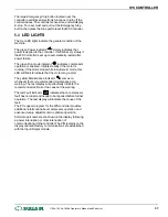
5.4 LED LIGHTS
The four LED lights indicate the general condition of the
machine.
The green Power indicator " " simply indicates that
power is applied to the controller. It will blink very slowly if
the WS Controller is set up to automatically restart after
power failure.
The green Run mode indicator " " indicates compressor
operation is enabled. It lights steadily if the motor is
running. If the motor stops while in Automatic mode, this
LED will blink to indicate that the motor may restart.
The yellow Maintenance indicator " " comes on
whenever there is recommended maintenance or a
warning. The text display will periodically indicate the
recommended actions or the cause of the warning.
The red Fault indicator "
" indicates that a compressor
fault has occurred and needs to be repaired before further
operation. The text display will indicate the cause of the
fault.
The PC support program for the WS controller provides
additional information about compressor operation and
advanced setup adjustments to optimize operation.
Software part numbers are shown in the display following
a power interruption or other interruption of
communication with the controller. The P/N remains on the
display until satisfactory communications are established
with the Input/Output module.
WS CONTROLLER
®
SULLAIR
®
1100e, 1500e, 1800e Operator’s Manual and Parts List
37
Содержание 1107e
Страница 13: ...THIS PAGE INTENTIONALLY LEFT BLANK DESCRIPTION SULL AIR 1100e 1500e 1800e Operator s Manual and Parts List 9...
Страница 34: ...SECTION 3 THIS PAGE INTENTIONALLY LEFT BLANK 30 1100e 1500e 1800e Operator s Manual and Parts List SULL AIR...
Страница 42: ...SECTION 5 THIS PAGE INTENTIONALLY LEFT BLANK 38 1100e 1500e 1800e Operator s Manual and Parts List SULL AIR...
Страница 50: ...SECTION 6 THIS PAGE INTENTIONALLY LEFT BLANK 46 1100e 1500e 1800e Operator s Manual and Parts List SULL AIR...
Страница 58: ...7 4 AIR INLET SYSTEM 02250157_200r02 SECTION 7 54 1100e 1500e 1800e Operator s Manual and Parts List SULL AIR...
Страница 62: ...7 6 FLUID PIPING 02250154 767R003 SECTION 7 58 1100e 1500e 1800e Operator s Manual and Parts List SULL AIR...
Страница 68: ...7 9 MOISTURE DRAIN 02250157_143R00 SECTION 7 64 1100e 1500e 1800e Operator s Manual and Parts List SULL AIR...
Страница 84: ...7 14 ENCLOSURE 02250155_649R05 SECTION 7 80 1100e 1500e 1800e Operator s Manual and Parts List SULL AIR...
Страница 100: ...SECTION 7 THIS PAGE INTENTIONALLY LEFT BLANK 96 1100e 1500e 1800e Operator s Manual and Parts List SULL AIR...
Страница 101: ...THIS PAGE INTENTIONALLY LEFT BLANK...

