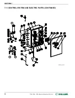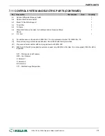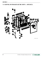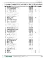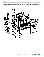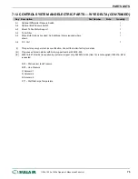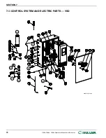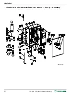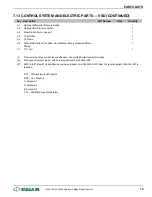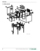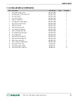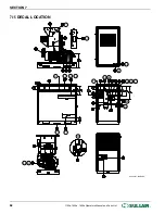
7.12 CONTROL SYSTEM AND ELECTRIC PARTS — WYE DELTA (CONTINUED)
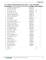
Key Description
Part Number
Note
Quantity
1
switch, differential pressure 20psid 12ft or
02250050–154
1
2
tube, nyl .25 od x 040w blk(ft)
02250054–861
1
3
grip, cord n4 .125–.187 x 1/2”
02250071–379
(III)
2
4
grip, cord n4 .187–.250 x 1/2”
02250071–380
(III)
1
5
grip, cord n4 .250–.375 x 1/2”
02250071–381
(III)
2
6
switch, vacuum 22”wc n4 6ft cable 5a
02250078–249
1
7
nameplate, e–stop 45mm yellow
02250081–473
1
8
switch, push–button operator e22 40 mm
02250085–504
1
9
bar, ground 5 post cutler hammer
02250101–721
2
10
block, pwr distr 600a
02250145–195
(IV)
1
11
control, display s4
02250154–051
1
12
control, i/o mod ws 24vdc supply
02250154–052
1
13
decal, microprocessor overlay
02250154–359
1
14
block, contact aux 1 no ch–it a–e
02250154–607
1
15
block, contact aux 1 nc ch–it a–e
02250154–608
2
16
transducer, pressure 0–250# ratiometric
02250155–174
2
17
proble, rtd 100 ohm plat 3.5”x6ft
02250155–175
1
18
link, mech intrik ch it frm b–e
02250155–676
1
19
specification, encl 2200 19” x 24.5” x 7
02250156–385
1
20
wire, 10 gauge ground bond 12” m8
02250157–450
1
21
receptacle, s4 program port nema 6p
02250159–547
1
22
cap, s4 program port nema 6–
02250159–549
1
23
spacer, p8/12 ws mtg to encl.
02250161–759
4
24
breaker, cir100a hmcp
250014–827
(IV)
1
25
conn, 1/4” tube x 1/8” npt
250018–427
1
26
elbow, 90 1/4”tube x 1/8”npt
250018–429
3
27
relay, overload 32a
250021–692
1
28
adapter, o.l.r.bse mnt ch1
250021–694
1
29
connector, cord grip 0.09–0.26
250023–496
1
30
elbow, 90deg m swvl 1/4t x 1/8npt
250025–849
1
31
connector, male 1/4tube x 1/8
250025–858
1
32
block, contact 1nc
250027–125
1
33
fitting, compress adj
250028–635
1
34
nut, hex metric m8 x 1.25
825908–125
6
35
washer, spr lock–metric pltd m8
838808–200
6
36
tubing, st stl 1/4” 20 ga
841215–004
1
37
lug, scrulug kpa–25 4–1/0
849215–025
1
38
terminal, ring tng 3/8 x 8ga
849306–008
1
39
washer, metric–ISO7089–8
865408–170
6
40
starter, ac
–
(I)
1
41
contactor
–
(I)
2
42
supply, power
–
(I)
1
PARTS LISTS
®
SULLAIR
®
1100e, 1500e, 1800e Operator’s Manual and Parts List
73
Содержание 1107e
Страница 13: ...THIS PAGE INTENTIONALLY LEFT BLANK DESCRIPTION SULL AIR 1100e 1500e 1800e Operator s Manual and Parts List 9...
Страница 34: ...SECTION 3 THIS PAGE INTENTIONALLY LEFT BLANK 30 1100e 1500e 1800e Operator s Manual and Parts List SULL AIR...
Страница 42: ...SECTION 5 THIS PAGE INTENTIONALLY LEFT BLANK 38 1100e 1500e 1800e Operator s Manual and Parts List SULL AIR...
Страница 50: ...SECTION 6 THIS PAGE INTENTIONALLY LEFT BLANK 46 1100e 1500e 1800e Operator s Manual and Parts List SULL AIR...
Страница 58: ...7 4 AIR INLET SYSTEM 02250157_200r02 SECTION 7 54 1100e 1500e 1800e Operator s Manual and Parts List SULL AIR...
Страница 62: ...7 6 FLUID PIPING 02250154 767R003 SECTION 7 58 1100e 1500e 1800e Operator s Manual and Parts List SULL AIR...
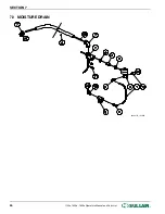
Страница 68: ...7 9 MOISTURE DRAIN 02250157_143R00 SECTION 7 64 1100e 1500e 1800e Operator s Manual and Parts List SULL AIR...
Страница 84: ...7 14 ENCLOSURE 02250155_649R05 SECTION 7 80 1100e 1500e 1800e Operator s Manual and Parts List SULL AIR...
Страница 100: ...SECTION 7 THIS PAGE INTENTIONALLY LEFT BLANK 96 1100e 1500e 1800e Operator s Manual and Parts List SULL AIR...
Страница 101: ...THIS PAGE INTENTIONALLY LEFT BLANK...

