


5. Reconnect the motor leads and jog the motor for a
direction of rotation check as explained in Motor
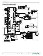
Rotation Direction Check on page 34. Wiring
diagram for standard compressors is supplied with the
machine.
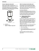
4.7 MOTOR ROTATION DIRECTION
CHECK
Motor rotation check must be made at compressor start-
up. The compressor will not operate correctly if it runs in
the wrong direction. Open the compressor door to view the
motor rotation. After the electrical wiring has been done, it
is necessary to check the direction of the motor rotation.
Pull out the EMERGENCY STOP button and press once,
quickly and in succession, the “
” (START) and
“
” (STOP) pads. This action will bump start the motor
for a very short time. When looking at the motor from the
end opposite the compressor unit, the shaft should be
turning clockwise. If the reversed rotation is noted,
disconnect the power to the starter and exchange any two
of the three power input leads, then re-check rotation. A
“Direction of Rotation” decal is located on the motor drive
housing to show proper motor/compressor rotation. An
alternative to this procedure is to set the WS Controller to
display P1 receiver tank pressure. Pull out the
EMERGENCY STOP button and press once, quickly and
in succession, the “
” (START) and “
” (STOP) pads.
This action will bump start the motor for a very short time.
If motor rotation is correct there will be immediate pressure
shown. If no pressure is present, reverse rotation is
occurring. Disconnect the power to the starter and
exchange any two of the three power input leads. Recheck
rotation as outlined above.
4.8 FAN MOTOR ROTATION CHECK
On initial start-up check that the fan is rotating in the proper
direction. The correct rotation is counterclockwise when
viewing the fan motor from the driveshaft end.
SECTION 4
34
1100e, 1500e, 1800e Operator’s Manual and Parts List
®
SULLAIR
®
Содержание 1107e
Страница 13: ...THIS PAGE INTENTIONALLY LEFT BLANK DESCRIPTION SULL AIR 1100e 1500e 1800e Operator s Manual and Parts List 9...
Страница 34: ...SECTION 3 THIS PAGE INTENTIONALLY LEFT BLANK 30 1100e 1500e 1800e Operator s Manual and Parts List SULL AIR...
Страница 42: ...SECTION 5 THIS PAGE INTENTIONALLY LEFT BLANK 38 1100e 1500e 1800e Operator s Manual and Parts List SULL AIR...
Страница 50: ...SECTION 6 THIS PAGE INTENTIONALLY LEFT BLANK 46 1100e 1500e 1800e Operator s Manual and Parts List SULL AIR...
Страница 58: ...7 4 AIR INLET SYSTEM 02250157_200r02 SECTION 7 54 1100e 1500e 1800e Operator s Manual and Parts List SULL AIR...
Страница 62: ...7 6 FLUID PIPING 02250154 767R003 SECTION 7 58 1100e 1500e 1800e Operator s Manual and Parts List SULL AIR...
Страница 68: ...7 9 MOISTURE DRAIN 02250157_143R00 SECTION 7 64 1100e 1500e 1800e Operator s Manual and Parts List SULL AIR...
Страница 84: ...7 14 ENCLOSURE 02250155_649R05 SECTION 7 80 1100e 1500e 1800e Operator s Manual and Parts List SULL AIR...
Страница 100: ...SECTION 7 THIS PAGE INTENTIONALLY LEFT BLANK 96 1100e 1500e 1800e Operator s Manual and Parts List SULL AIR...
Страница 101: ...THIS PAGE INTENTIONALLY LEFT BLANK...