Pressure Regulator Adjustment
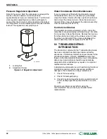
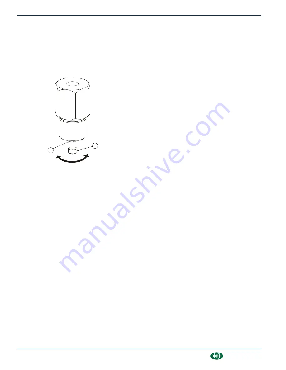
Refer to Figure 6-4. Start the compressor and adjust the
service valve to maintain service air pressure
approximately at 5 psi over rated pressure. Turn the inlet
valve regulator adjusting screw until air just begins to
escape from the control air orifice (located at the bottom
of the regulator). Lock the adjusting screw in place with the
locknut. The regulator is now properly set.
1
2
SU_0000033
1. Locking Nut
2. Adjustment Screw
Figure 6-4: Regulator Adjustment
Water Condensate Drain Maintenance
If your compressor is fitted with the standard solenoid
condensate drain valve, it is necessary to periodically
clean the strainer. Remove the hex cap from the strainer
and remove the strainer screen. Clean the screen and
reinstall. If the screen is damaged, the strainer assembly
must be replaced (P/N 241772).
Control Line Strainer
The regulator and solenoid valve(s), which control the
compressor, are protected by a strainer. Every 12 months
it is necessary to clean the strainer. Remove the hex cap
from the strainer and remove the strainer screen. Clean
the screen and reinstall. If the screen is damaged, the
strainer assembly must be replaced (P/N 241772).
6.8 TROUBLESHOOTING -
INTRODUCTION
The information contained in the Troubleshooting Guide
has been compiled from field report data and factory
experience. It contains symptoms and usual causes for the
described problems. However, DO NOT assume that
these are the only problems that may occur. All available
data concerning a problem should be systematically
analyzed before undertaking any repairs or component
replacement procedures.
A detailed visual inspection is worth performing for almost
all problems and may avoid unnecessary additional
damage to the compressor. Always remember to:
1. Check for loose wiring.
2. Check for damaged piping.
3. Check for parts damaged by heat or an electrical short
circuit, usually apparent by discoloration or a burnt
odor.
Should your problem persist after making the
recommended check, consult your nearest Sullair
representative.
SECTION 6
42
1100e, 1500e, 1800e Operator’s Manual and Parts List
®
SULLAIR
®
Содержание 1107e
Страница 13: ...THIS PAGE INTENTIONALLY LEFT BLANK DESCRIPTION SULL AIR 1100e 1500e 1800e Operator s Manual and Parts List 9...
Страница 34: ...SECTION 3 THIS PAGE INTENTIONALLY LEFT BLANK 30 1100e 1500e 1800e Operator s Manual and Parts List SULL AIR...
Страница 42: ...SECTION 5 THIS PAGE INTENTIONALLY LEFT BLANK 38 1100e 1500e 1800e Operator s Manual and Parts List SULL AIR...
Страница 50: ...SECTION 6 THIS PAGE INTENTIONALLY LEFT BLANK 46 1100e 1500e 1800e Operator s Manual and Parts List SULL AIR...
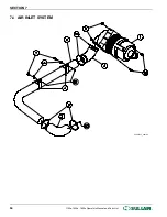
Страница 58: ...7 4 AIR INLET SYSTEM 02250157_200r02 SECTION 7 54 1100e 1500e 1800e Operator s Manual and Parts List SULL AIR...
Страница 62: ...7 6 FLUID PIPING 02250154 767R003 SECTION 7 58 1100e 1500e 1800e Operator s Manual and Parts List SULL AIR...
Страница 68: ...7 9 MOISTURE DRAIN 02250157_143R00 SECTION 7 64 1100e 1500e 1800e Operator s Manual and Parts List SULL AIR...
Страница 84: ...7 14 ENCLOSURE 02250155_649R05 SECTION 7 80 1100e 1500e 1800e Operator s Manual and Parts List SULL AIR...
Страница 100: ...SECTION 7 THIS PAGE INTENTIONALLY LEFT BLANK 96 1100e 1500e 1800e Operator s Manual and Parts List SULL AIR...
Страница 101: ...THIS PAGE INTENTIONALLY LEFT BLANK...

