


5. NOSE ASSEMBLIES
It is essential that the correct nose assembly is fitted prior to operating the tool. By knowing the details of the fastener to be
placed, you will be able to order a new complete nose assembly using the selection tables on page 13.
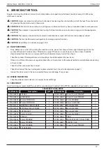
5.1 FITTING INSTRUCTIONS
CAUTION
: The air supply must be disconnected when fitting or removing nose assemblies unless specifically instructed
otherwise.
Item numbers in
bold
refer to illustration below:
•
If still fitted remove the nose casing and the adaptor nut.
•
Insert drive shaft
4
into spindle.
•
Fit drive screw
3
onto drive shaft
4
.
•
Insert reducing sleeve
5
(if specified) into the adaptor nut.
•
Screw the adaptor nut onto the spindle.
•
Hold the spindle with a spanner* and tighten the adaptor nut clockwise.
•
While holding the adaptor nut with the spanner*, tighten the lock nut anti-clockwise.
•
Screw on the nose casing and nose tip
1
with the nose tip lock nut.
•
The reverse operation is carried out for equipment removal.
•
With tool still disconnected from air supply, screw one insert onto drive screw manually - making sure the insert is flush
with the end of drive screw.
•
Set nose tip in exact position and lock nose tip nut clockwise with a spanner*.
•
Remove the insert from drive screw.
Fig. 4
LOCK NUT
ADAPTOR NUT
NOSE CASING
Items in grey are included in the base tool.
Items in black make up the nose assembly.
SPINDLE
FRICTION RING
5.2 SERVICE INSTRUCTIONS
Nose assemblies should be serviced at weekly intervals.
•
Remove the complete nose assembly using the reverse procedure to the ‘Fitting Instructions’.
•
Any worn or damaged part should be replaced by a new part.
•
Particularly check wear on drive screw.
•
Assemble according to fitting instructions.
Refers to items included in the 74200 service kit. For complete list see page 13.
5.3 74200 NOSE ASSEMBLY COMPONENTS
Nose tips vary in shape according to the insert type. Each nose assembly represents a unique assembly of components
which can be ordered individually. All nose assemblies also include a nose tip locknut 2 (part number 07555-00901).
Component numbers refer to the illustration on the opposite page. We recommend some stock as items will need regular
replacement. Read the Nose Assemblies servicing instructions opposite carefully.
10
ENGLISH
ORIGINAL INSTRUC TION
Содержание Avdel 74200
Страница 18: ...7 GENERAL ASSEMBLIES 7 1 GENERAL ASSEMBLY OF BASE TOOL 74200 12000 18 ENGLISH ORIGINAL INSTRUCTION ...
Страница 68: ...7 OPĆI SKLOPOVI 7 1 OPĆI SKLOP OSNOVNOG ALATA 74200 12000 68 HRVATSKI PRIJEVOD IZVORNIH UPUTA ...
Страница 92: ...7 ZÁKLADNÍ SESTAVY 7 1 CELKOVÁ SESTAVA ZÁKLADNÍHO NÁŘADÍ 74200 12000 92 ČESKY PŘEKLAD Z ORIGINÁLNÍCH POKYNŮ ...
Страница 164: ...7 CELKOVÉ ZOSTAVY 7 1 CELKOVÁ ZOSTAVA ZÁKLADNÉHO NÁRADIA 74200 12000 164 SLOVENČINA PREKLAD Z ORIGINÁLNYCH POKYNOV ...
Страница 188: ...7 SPLOŠNO SESTAVLJANJE 7 1 SPLOŠNO SESTAVLJANJE ORODJA PODSTAVKA 74200 12000 188 SLOVENŠČINA PREVOD IZVIRNIH NAVODIL ...
Страница 214: ...7 ОБЩАЯ СБОРКА 7 1 СБОРОЧНЫЙ ЧЕРТЕЖ ОСНОВНОГО ИНСТРУМЕНТА 74200 12000 214 РУССКИЙ ПЕРЕВОД ОРИГИНАЛЬНОЙ ИНСТРУКЦИИ ...
Страница 223: ...223 ПЕРЕВОД ОРИГИНАЛЬНОЙ ИНСТРУКЦИИ РУССКИЙ ...
Страница 288: ...7 BENDRIEJI MAZGAI 7 1 BENDRASIS BAZINIO ĮRANKIO 74200 12000 MAZGAS 288 LIETUVIŠKAI ORIGINALO INSTRUKCIJŲ VERTIMAS ...
Страница 312: ...7 KOOSTEJOONISED 7 1 KOOSTEJOONIS PÕHISEADE 74200 12000 312 EESTI KEEL ORIGINAALJUHENDI TÕLGE ...
Страница 347: ...347 ΜΕΤΑΦΡΑΣΗ ΤΟΥ ΠΡΩΤΟΤΥΠΟΥ ΤΩΝ ΟΔΗΓΙΩΝ ΕΛΛΗΝΙΚΆ ...
Страница 364: ...7 GENEL KURULUMLAR 7 1 TABAN ALETİNİN GENEL KURULUMU 74200 12000 364 TÜRKÇE ORİJİNAL KILAVUZDAN ÇEVİRİ ...


