ST 500 "Piranha" Operation Manual: Low Frequency Amplifier Channel
45
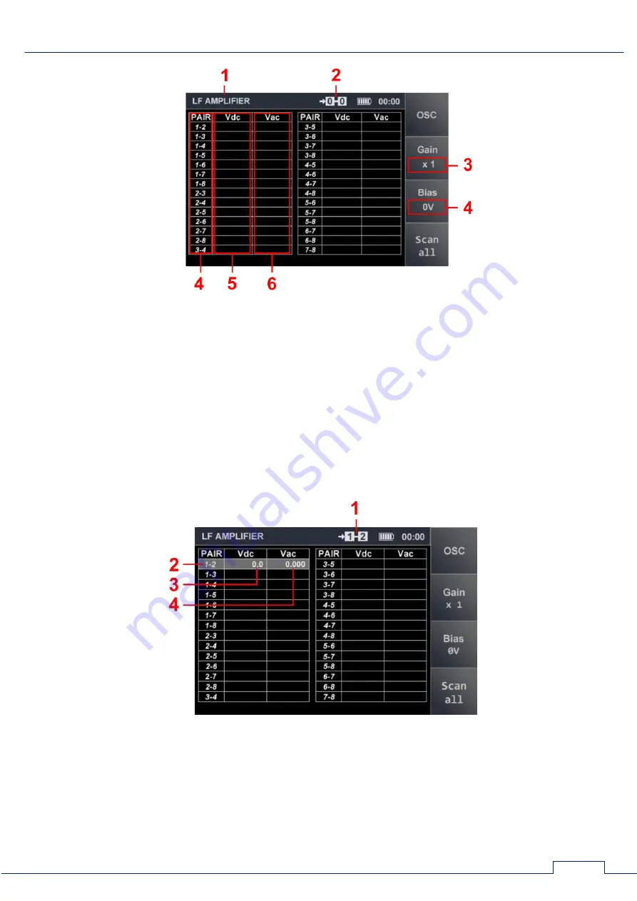
Fig.40
In fig.40:
1 - active channel
2 - pair of wires connected
3 - gain selected
4 - bias voltage selected
5 - wire pairs
6 - measured values of direct voltage
7 - measured values of alternating voltage
The measured values of direct and alternating voltage are shown for the pair of wires that is
currently selected in the table (fig.41).
Fig.41
In fig.41:
1 - connected pair of wires
2 - current table row
3 - the value of the DC voltage
4 - the value of the AC voltage


