3-12
Installing the Servo Drive
07-01-08-02-E-V0500 631 Digital Servo Drive
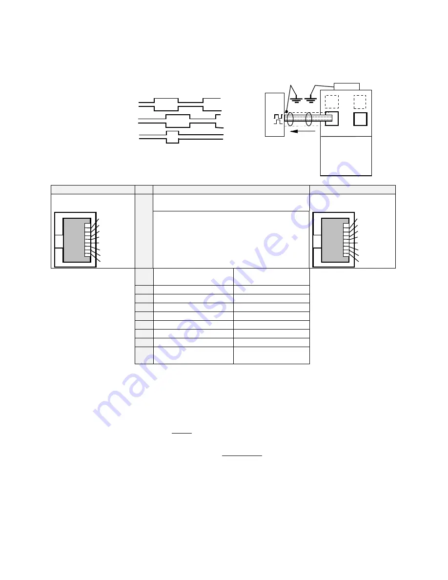
X40/41 Mode 0 - Incremental Output
•
Incremental encoder simulation for processing in positioning modules
•
Standard: 1024 increments; other selectable pulse numbers are 512, 256, 128
A
/B
B
Z
/A
/Z
Incremental Encoder inputs or outputs
X40
X41
631
Incremental OUT
PLC
IN
Encoder Emulation,
based on Resolver
conversion
GND
X40
X40
X40
X40
Pin
Pin
Pin
Pin
Function
Function
Function
Function
X41
X41
X41
X41
8-pole Modular Jack,
screened
EASYRIDER
<
X40 mode = 0
8-pole Modular Jack,
screened
1
8
GND
/Z
Z
/B
B
/A
A
5VI
X40 and X41 are identical and internally switched
in parallel.
(X40 = X41) therefore wiring is very easy.
1
8
GND
/Z
Z
/B
B
/A
A
5VI
internal connection to
GND
Case: Screened
1
11
1
GND
2
22
2
inverted 0-Index
OUT /Z
3
33
3
0-Index
OUT Z
4
44
4
Channel B inverted
OUT /B
5
55
5
Channel B
OUT B
6
66
6
Channel A inverted
OUT /A
7
77
7
Channel A
OUT A
8
88
8
Output supply voltage
5.5V dc max. 150mA
5VI
Design Rule
The capability of input frequency of any connected device must at least meet the selected value
of pulse outputs (increments) on X40.
n = maximum speed (rpm)
x = increments e.g. 1024
f = output frequency at X40/41 4,5,6,7
Formula:
f =
n * x
50
= [Hz]
Example: n = 4000 rpm
f =
4 0 0 0 * 1 0 2 4
5 0
= 8 1 9 2 0 H z


