SS-16 VoIP-2-GSM USER MANUAL
DOC. NO: SS-16-14 (REV. 02)
Page 13 of 84
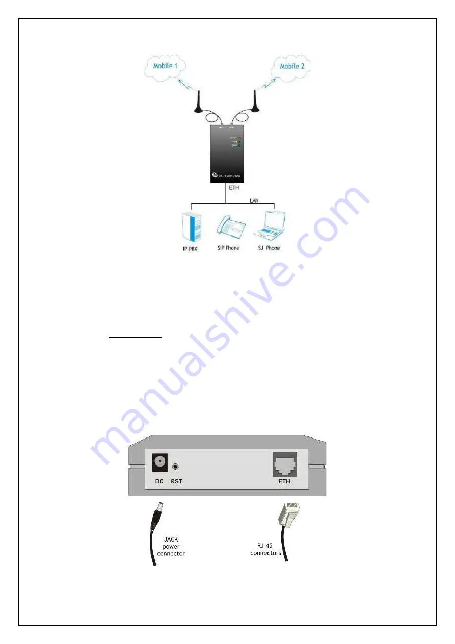
Figure 3: Connecting the LAN cable (UTP- CAT5)
The network cable is to be inserted with one end into the RJ-45 socket of the SS-16
VOIP-2-GSM device labelled
ETH
. The opposite end of the UTP cable can be
inserted directly into a PC or in switches or hubs. The STATUS indicator LED of the
SS-16 case will light up showing physical connection and data traffic on the
respective Ethernet interface.
Power supply:
To power the SS-16 VOIP-2-GSM unit, insert the jack of the power supply adapter
into the supply connector. Do
not
yet plug the adapter into the 230V
A.C.
mains outlet
on the wall. The special adapter from SS Telecoms, which is part of the SS-16 VOIP-
2-GSM package, supplies the voltage required to power the equipment. It is an
external power supply adapter.
Note:
The adapter is the disconnection device (there is no POWER switch),
so the 230 V
AC
socket-outlet shall be installed near the equipment and shall be
easily accessible.
Figure 4: Connecting the power supply


