8
www.spokey.pl
www.spokey.pl
18
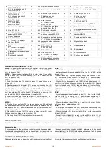
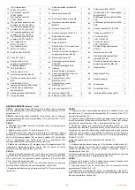
Front pedal supporter cover 1
125.1×36.7×89.4
2
55
Tension pulley Φ38×22
1
88
Deep groove ball bearing 6200-2RS 4
19
Front pedal supporter cover 2
125.1×39.7×89.4
2
56
Circlip shaft Φ10
1
89
Foam grip Φ36×t3.0×720
2
20
Rear pedal supporter cover 1
107.7×103×34.5
2
57
End cap 45×90×t1.5
4
90
Pipe plug Φ32×t1.5
2
21
Rear pedal supporter cover 2
107.7×103×37.5
2
58
Feet pad Φ49×22×M10×26
4
91
Motor cover(L) 1291.1×72×616.2
1
22
Handlebar cover(L)
209.1×147.5×57.5
1
59
Wheels Φ55×25.8
2
92
Motor cover(R) 1291.1×75.9×616.2 1
23
Handlebar cover(R)
209.1×147.5×60.5
1
60
Allen C.K.S. hollow screw
Φ8×33×M6×15
2
93
Philips C.K.S. Self-tapping screw
ST4×25
5
24
Bottle holder Φ93×150
1
61
Hex full thread screw M5×60
1
94
Circlip for holes Φ40
2
25
Axle Φ17×339.5
1
62 Hex nut M5
2
95
Self-aligning ball bearing 2203-2RS 2
26
Allen C.K.S. half thread screw
M10×60×20
4
63
Deep groove ball bearing 6004-
2RS
2
96
Hex full thread screw M8×120
1
28
Curved washer
Φ10.5×R128×t1.5
5
64 Fixed magnetic induction
1
97
Power communication wire
1
29
Allen C.K.S. full thread screw
M8×20 -left
13
65
Philips washer head end-cuttin
self-
tapping screw ST4×12
1
98
Magnetic sensor
1
32
Hex self-locking nut M10
3
66
Crank axle sleeve 1
Φ25×Φ20.1×4.6
1
99
Power adapter
1
33
Allen C.K.S. full thread screw
M10×55×20
1
67
Crank axle sleeve 3
Φ40×Φ20.1×7.7
1
100 Brake line
1
52
Idler connecting shaft Φ15×30
1
68
Crank axle Φ20×115
1
101
Disc Φ466.6×24.1
2
53
Hex nut M8
2
86
Allen C.K.S. full thread screw
M6×12
8
102
Waved spring washer Φ17
2
54
Hex locking nut M8
7
87
Deep groove ball bearing 6003-
2RS
4
INSTALLATION INSTRUCTIONS
(Drawings
– p.
46
)
STEP 1
Attach the front stabilizer (2) to the main frame (1) with curved
washer(28), springwasher(27) and Allen C.K.S. half thread screw(26).
STEP 2
Attach the rear stabilizer (3) to the main frame (1) with curved
washer(28), spring washer(27) and Allen C.K.S. half thread screw(26).
STEP 3
1.Take upright post cover(15) off from the main frame(1) and cover it on
the upper upright post.(4)
2.Connect motor communication wire(11) and console communication
wire.(12)
3.Attach upper upright post(4) to the main frame(1) with flat washer(31),
spring washer(30), Allen C.K.S. full thread screw(29) and flat washer(34),
spring washer(27), Allen C.K.S. half thread screw(35) and Allen C.K.S. half
thread screw(33), curved washer(28), Hex self-locking nut(32).
4.Attach upright post cover(15) to the main frame(1) and install the
Axle(25).
Tip:Do not fully tighten the Bolt yet. Make sure that all screws are in the
hexagonal hole
STEP 4
1. Assemble the waved spring washers (102) to the left and right Axle (25).
then attach left body arm(5) and right body arm(6) to the left Axle(25) and
right Axle(25) with flat washer(31)and Allen C.K.S. full thread screw(29).
2.Attach arm cover(16/17) to the left body arm(5) with Philips pan head full
thread screw(36).
3.Repeat the last step to attach cover(16/17) to the right body arm(6).
STEP 5
1.Attach the axle sleeve of left rear pedal supporter(7) to the axle of main
frame(1) with Flat washer (31) and Allen C.K.S. full thread screw(29).
2.Attach the axle sleeve of left front pedal supporter(7) to left body arm(5)
with Allen C.K.S. hollow screw(38), flat washer(39) and Allen C.K.S. full
thread screw(40).
3.Attach the rear cover of pedal supporter(20/21) to left pedal supporter(7)
with Philips pan head full thread screw(36). Attach the front cover of pedal
supporter(18/19) to left pedal supporter(7) with Philips pan head full
thread screw(37) and Philips C.K.S. self-tapping screw(41).
4.Install right pedal supporter(8) with the same way.
STEP 6
1.Through handle pulse connection wire(13) out of the upper upright
post(4). Attach handlebars(9) to upright post(4) with flat washer(31), spring
washer(30) and Philips pan head full thread screw(36).
2.Attach bottle holder(24) to upper upright post(4) with Philips pan head full
thread screw(36).
STEP 7
1.Connect console communication wire(12) with the interface of back
console. Connect handle pulse communication wire (13) with console
outset(14).
2.Attach console(10) to upper upright post(4) with Philips C.K.S. self-
tapping screw(41).
3.Through left handlebar cover(22) and right handlebar cover(23) out of the
handlebar(9). Attach them to the upper upright post(4) with Philips pan
head full thread screw(36).
Moving the device
Raise the trainer carefully onto its transport wheels (Picture
– p. 51) and move to a given place, holding it on both sides.
Resistance adjustment
The function of intensity regulation allows you to change pedal resistance.
High resistance requires a greater effort during pedalling while a low one
reduces the needed effort. Resistive force can be regulated by means of
the computer. To achieve a satisfying result, intensity should be adjusted
during workout, by means of knob UP (+) and DOWN (-).Available
resistance levels: from 1 to 32. The load system is independent of speed.
Levelling (drawing
– p.51)
Before you start exercising, it is recommended to verify whether the bike is positioned correctly.
Level the equipment with the knobs of the rear stabilizer.
Содержание 836447
Страница 2: ...1 www spokey pl www spokey eu ...
Страница 44: ...43 www spokey pl www spokey eu 1 ...
Страница 45: ...44 www spokey pl www spokey eu SCHEMAT DIAGRAM СХЕМА SCHÉMA SCHEMA SHĒMA SCHEMA ...
Страница 48: ...47 www spokey pl www spokey eu 3 KROK STEP ШАГ ŽINGSNIS SOLIS SCHRITT 26 28 32 29 33 35 ...
Страница 49: ...48 www spokey pl www spokey eu 4 KROK STEP ШАГ ŽINGSNIS SOLIS SCHRITT 29 36 ...
Страница 51: ...50 www spokey pl www spokey eu 7 KROK STEP ШАГ ŽINGSNIS SOLIS SCHRITT 42 36 ...
Страница 53: ...52 www spokey pl www spokey eu 1 2 3 4 5 6 7 8 9 ...
Страница 54: ...53 www spokey pl www spokey eu 2 ...


