


Installation and Reference Manual
System Operation
48
Installation and Reference Manual v3.2/0410/6
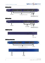
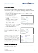
4100 Call Server
1
Remove the lid
2
Place nylon standoffs supplied in mounting holes located by silk screen logos MTG14 and MTG15.
3
Fit VCC card to connector J12 and standoffs - take care to correctly align the pins.
4
Replace the lid.
4140 Remote Call Server
1
Remove the lid
2
Place nylon standoffs supplied in mounting holes located by silk screen logos MTG9 and MTG10.
3
Fit VCC card to connector J11 and standoffs - take care to correctly align the pins.
4
Replace the lid.
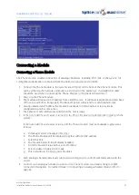
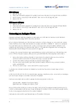
Connecting an Analogue Phone
Analogue extension ports are available on 5100 Call Server, 4140 Remote Call Server and 5300/4300
Phone Modules providing 16/8/15/30 ports respectively.
When a 5100 or 5108 Call Server, 4140 Remote Call Server or Phone Module is connected to the system
4/8/15/16/30 Users are created and named, for example, Extn2001, Extn2002 etc. Each User is assigned
to an extension port, for example, Port 1, Port 2 etc, and given an extension number within the next
available extension range, for example, 2001, 2002 etc. This default configuration can be changed as
detailed within the Working with Users section from page 80.
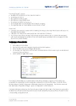
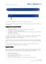
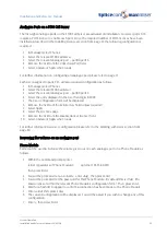
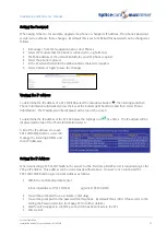
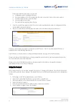
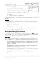
To change the extension number range automatically used when a 5100 Call Server, 4140 Remote Call
Server or Phone Module registers with a system, eg to 6001-6030, the following steps can be taken:
1
Before the Call Server/Phone Module is connected to the system create a new User with an
extension number one before the start of the range required, eg 6000
2
Connect the Call Server/Phone Module as described from page 39.
3
The new Users created will be given an extension number within the new extension number
range, eg 6001-6030.
4
The User created in step 1 can be deleted if no longer required.
To change the extension numbers for multiple Users after they have been created please refer to
page 84.
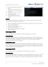
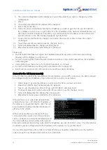
A PCS 520, PCS 505, PCS 10, PCS 5 or an alternative analogue telephone can be connected to an analogue
port via a master dongle or via a RJ45 connection if supplied.
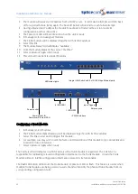
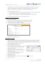
Each port is provided with two LEDs to display the following activity on the port:
Left hand LED = displays when phone ringing
Right hand LED = displays when phone in use
When a 5100 or 4140 Call Server or Phone Module is rebooted each analogue handset will ring once to
confirm communication with the system and will display the number of new voicemail messages waiting
for the User assigned to that phone (if voicemail enabled).
Calls placed on hold will be automatically taken off hold after 10 minutes.
Содержание Maximiser
Страница 1: ...Installation Reference Manual Version 3 2 April 2010 ...
Страница 6: ......
Страница 363: ......


