RadioProcessor
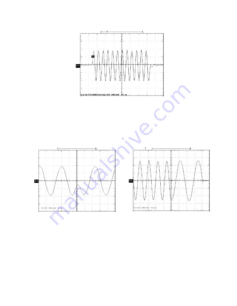
To demonstrate the zero-latency phase- and frequency-switching agility, two short back-to-back pulses
were recorded - with a 180-degree phase offset (Figure A1.2, left panel, 70 MHz RF, expanded view), and with
a frequency shift from 20 MHz to 10 MHz (Figure A1.2, right panel).
The standard gain output amplifier of the RadioProcessor is DC-coupled, and the frequency response of
the entire Tx section is within 3dB from DC to 85 MHz. RadioProcessor can generate RF pulses in this entire
range, while maintaining the required phase coherence with the receiving section through the use of a
common frequency source.
2020-10-07
32
Figure A1.1:
185 ns 70 MHz RF/IF output pulse.
Figure A1.2:
Two RF output pulses, back to back, with 180 degree phase switch and 70 MHz RF frequency
(left panel), and frequency shift from 20 MHz to 10 MHz (right panel).
www.spincore.com


