RadioProcessor
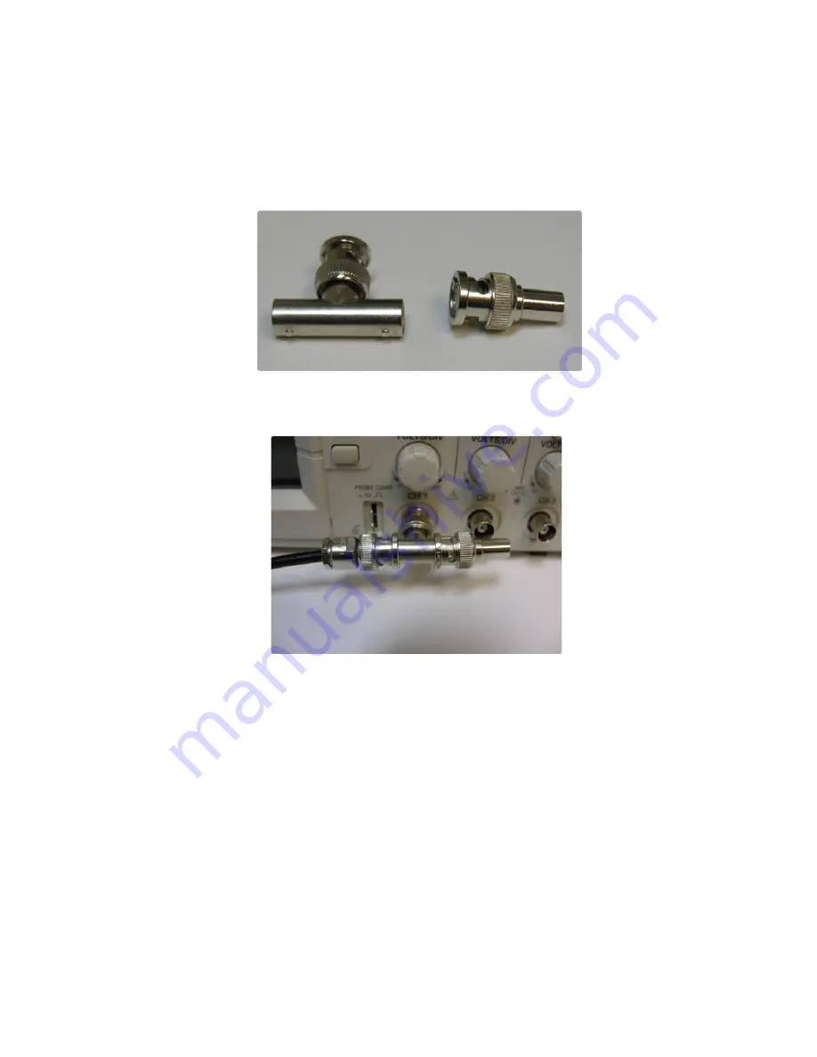
If using a high input impedance oscilloscope to monitor the RadioProcessor's output, place a resistor that
matches the characteristic impedance of the transmission line in parallel with the coaxial transmission line at
the oscilloscope input. (e.g., a 50 Ω resistor with a 50 Ω transmission line, see Figures 5 and 6 below.). When
using an oscilloscope with an adjustable bandwidth, set the bandwidth to as large as possible. Failure to do
so may yield inaccurate readouts on the oscilloscope.
Once this behavior has been verified, the user can be confident the board is installed properly and may
move on to evaluation of the acquisition subsystem. If the RadioProcessor is to be used to perform NMR
experiments, the easiest way to do this is to use the provided
singlepulse_nmr
example program. The
use of this program is described in detail in the next section.
2020-10-07
12
Figure 5:
Left: BNC T-Adapter and Right: BNC 50 Ohm resistor.
Figure 6:
BNC T-Adapter on the oscilloscope with coaxial transmission line connected
on the left and BNC 50 Ohm resistor connected on the right, to terminate the line.
www.spincore.com


