


6
TA-DA9000ES
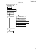
Note:
Follow the disassembly procedure in the numerical order given.
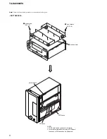
– BOTTOM VIEW –
1
nine screws
(BV3
×
8)
2
nine screws
(BV3
×
8)
3
bottom plate
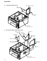
mother board
FSP board
DC board
NOTE:
•
FSP board can be removed in this state.
•
In the same state after removing a FSP board,
the check of DC board can be performed.
Содержание TA-DA9000ES
Страница 16: ...16 TA DA9000ES 3 10 MOTHER BOARD 1 four screws transistor 3 mother board 2 heat sink ...
Страница 22: ...MEMO TA DA9000ES 22 ...
Страница 193: ...193 TA DA9000ES MEMO ...