133
TA-DA9000ES
•
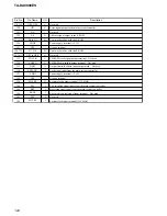
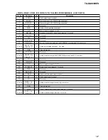
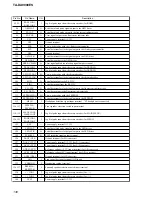
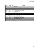
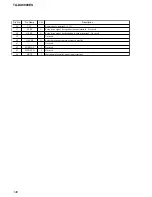
I. LINK BOARD IC3002 M30626FHPFP-DA9000ES (I. LINK SYSTEM CONTROLLER)
Pin No.
Pin Name
I/O
Description
1 to 7
HD6 to HD0
I/O
Two-way data bus with the i. link DSP
8
BYTE
I
External data bus line byte selection signal input terminal
“L”: 16 bit, “H”: 8 bit Fixed at “L” in this set
9
CNVSS
—
Processor mode selection signal input terminal “L”: single Fixed at “L” in this set
10
UN-MUTE
O
Muting on/off control signal output terminal
11
NC
O
Not used
12
RESET
I
System reset signal input from the main system controller “L”: reset
13
XOUT
O
System clock output terminal (10 MHz)
14
VSS
—
Ground terminal
15
XIN
I
System clock input terminal (10 MHz)
16
VCC
—
Power supply terminal (+3.3V)
17
NMI
I
Non-maskable interrupt input terminal Not used
18
MILES AUDIO
O
PCM audio data output to the DSP1
19
AKE_XF
I
External flag signal input from the i. link DSP
20
XHINT
O
Interrupt signal output terminal Not used
21
HRDY
I
Ready signal input from the i. link DSP
22
XHAS
O
Address strobe signal output to the i. link DSP
23, 24
XHDS1, XHDS2
O
Data strobe signal output to the i. link DSP
25
XHCS
O
Chip select signal output to the i. link DSP
26
XRS
O
Reset signal output to the i. link DSP “L”: reset
27, 28
NC
O
Not used
29
IIC CLK
I
Serial data transfer clock signal input from the main system controller
30
IIC DATA
I/O
Two-way data bus with the main system controller
31
TXD1
I
Not used
32
RXD1
I
Not used
33
CLK1
I
Not used
34
RTS1
I
Not used
35
ERRCLR
O
Error output clear signal output terminal
36
STR/TA
I
Model setting terminal “L”: STR-DA9000ES, “H”: TA-DA9000ES
37, 38
NC
O
Not used
39
RDY
I
Ready signal input from the i. link interface
40
ALE
O
Not used
41
HOLD (PULL UP)
I
Not used
42
HLDA
O
Not used
43
BCLK
O
Not used
44
RD
O
Read data output to the EEPROM and i. link interface
45
WRH
O
Not used
46
WR
O
Write data output to the EEPROM and i. link interface
47
NC
O
Not used
48
EEP_CS
O
Chip select signal output to the EEPROM
49
CXD3210 CS
O
Chip select signal output to the i. link interface
50
NC
O
Not used
51, 52
HCNTL0, HCNTL1
O
Control signal output to the i. link DSP
53
HBIL
O
Byte identification signal output to the i. link DSP
54
HRW
O
Read/write signal output to the i. link DSP
Содержание TA-DA9000ES
Страница 16: ...16 TA DA9000ES 3 10 MOTHER BOARD 1 four screws transistor 3 mother board 2 heat sink ...
Страница 22: ...MEMO TA DA9000ES 22 ...
Страница 193: ...193 TA DA9000ES MEMO ...


