20
TA-DA9000ES
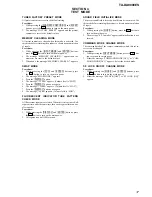
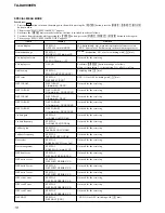
1. Connect a frequency counter to the CN1309 pin
1
on the
COMPONENT board.
2. Press the
I/
1
button to turn on the main power.
3. Perform the MEMORY CREARING MODE. (See page 17)
4. Press the
[ON SCREEN]
button on the remote commander (RM-
LJ312) to display “ON SCREEN [ON]”.
5. Turn the
[MAIN MENU]
dial to display “<< CUSTOMIZE >>”.
6. Turn the
[MENU]
dial to display “COLOR SYSTEM”.
7. Turn the
[--/+]
dial to select PAL.
8. Adjust the CT1304 so that the frequency counter reading is 7.20
MHz.
9. Connect a frequency counter to the CN1309 pin
2
on the
COMPONENT board.
10. Adjust the CT1302 so that the frequency counter reading is
4.433618 MHz
±
50 Hz.
11. Turn the
[--/+]
dial to select NTSC.
12. Adjust the CT1303 (AEP and UK models) or CT1301 (Taiwan
and Korean models) so that the frequency counter reading is
3.579545 MHz
±
50 Hz.
Note:
The steps 5 to 7, 10 and 11 should be performed to AEP and UK
models.
Adjustment and Connection Location:
OSD ADJUSTMENT
Connection
COMPONENT board
CN1309 pin
1
or pin
2
+
–
frequency counter
SECTION 5
ELECTRICAL ADJUSTMENTS
– COMPONENT BOARD (Component Side) –
CT1304
1
4
CT1301
CN1309
CT1302
CT1303
Содержание TA-DA9000ES
Страница 16: ...16 TA DA9000ES 3 10 MOTHER BOARD 1 four screws transistor 3 mother board 2 heat sink ...
Страница 22: ...MEMO TA DA9000ES 22 ...
Страница 193: ...193 TA DA9000ES MEMO ...

