121
TA-DA9000ES
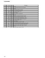
Pin No.
Pin Name
I/O
Description
112
A0
O
Address signal output to the S-RAM
113
PM
I
PLL initialize signal input from the main system controller
114, 115
SDI3, SDI4
I
Audio serial data input from the decimation filter
116
SYNC
I
Sync/non-sync setting terminal “L”: sync, “H”: non-sync Fixed at “H” in this set
117
TST2
O
Output terminal for the test Not used
118
VSS
—
Ground terminal
119
TST2
O
Output terminal for the test Not used
120
VDDI
—
Power supply terminal (+2.6V)
Содержание TA-DA9000ES
Страница 16: ...16 TA DA9000ES 3 10 MOTHER BOARD 1 four screws transistor 3 mother board 2 heat sink ...
Страница 22: ...MEMO TA DA9000ES 22 ...
Страница 193: ...193 TA DA9000ES MEMO ...


