130
TA-DA9000ES
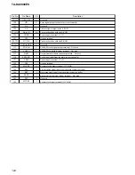
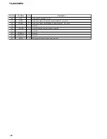
Pin No.
Pin Name
I/O
Description
92, 93
BASS JOG1,
BASS JOG2
I
Jog dial pulse input from the rotary encoder (for BASS)
94
OSD-LAT
O
Serial data latch pulse signal output to the OSD driver
95
FL-LAT
O
Serial data latch pulse output to the fluorescent indicator tube
96
FL-CLR
O
Clear signal output to the fluorescent indicator tube
97
VCC
—
Power supply terminal (+3.3V)
98
VSS
—
Ground terminal
99
SDA
I/O
Two-way data bus with the i-link system controller
100
SCL
O
Serial data transfer clock signal output to the i-link system controller
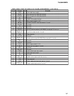
101
VSS
—
Ground terminal
102
OSD-CLK
O
Serial data transfer clock signal output to the OSD driver
103
OSD-DAT
O
Serial data output to the OSD driver
104
ERR/AUD-SEL
O
Error signal/audio data selection signal output terminal
105
TREB JOG1
I
Jog dial pulse input from the rotary encoder (for TREBLE)
106
TREB JOG2
I
Jog dial pulse input from the rotary encoder (for TREBLE)
107
UPCOM-DAT
I/O
Two-way data bus with the chroma decoder
108
UPCOM-CLK
O
Serial data transfer clock signal output to the chroma decoder
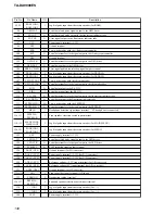
109
SOT1
O
Serial data output to the RS-232C
110
SIN1
I
Serial data input from the RS-232C
111
FL1-CLK
O
Serial data transfer clock signal output to the fluorescent indicator tube
112
FL1-DATA
O
Serial data output to the fluorescent indicator tube
113
EEPROM SDA
I/O
Two-way data bus with the EEPROM
114
EEPROM SCL
O
Serial data transfer clock signal output to the EEPROM
115
HP IN
I
Headphone detection signal input terminal “H”: headphone is connected
116, 117
FSPSW-A,
FSPSW-B
I
Front speaker selection switch input terminal
118, 119
MENU JOG1,
MENU JOG2
I
Jog dial pulse input from the rotary encoder (for MAIN MENU)
120, 121
PAGE JOG1,
PAGE JOG2
I
Jog dial pulse input from the rotary encoder (for MENU)
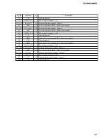
122
VCC
—
Power supply terminal (+3.3V)
123
LED LAT
O
Serial data latch pulse signal output to the LED driver
124
LED CLR
O
Serial data transfer clock signal output to the LED driver
125
PCM-SEL
O
PCM imitation signal output terminal
126
DAVS (VSS)
—
Ground terminal (for D/A converter)
127
DAVC (VCC)
—
Power supply terminal (+3.3V) (for D/A converter)
128
AVCC (VCC)
—
Power supply terminal (+3.3V) (for A/D converter)
129
AVRH (VCC)
—
Reference voltage (+3.3V) input terminal (for A/D converter)
130
AVRL (VSS)
—
Reference voltage (0V) input terminal (for A/D converter)
131
AVSS (VSS)
—
Ground terminal (for A/D converter)
132 to134
AD1
I
Front panel key input terminal (A/D input)
135
VERSION
I
Destination setting terminal
136, 137
RSPSW-A,
RSPSW-B
I
Surround speaker selection switch input terminal
138
+/– JOG1
I
Jog dial pulse input from the rotary encoder (for –/+)
139
+/– JOG2
I
Jog dial pulse input from the rotary encoder (for –/+)
140
VCC2
—
Power supply terminal (+3.3V)
Содержание TA-DA9000ES
Страница 16: ...16 TA DA9000ES 3 10 MOTHER BOARD 1 four screws transistor 3 mother board 2 heat sink ...
Страница 22: ...MEMO TA DA9000ES 22 ...
Страница 193: ...193 TA DA9000ES MEMO ...


