


137
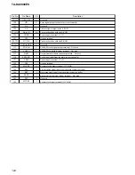
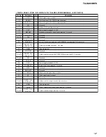
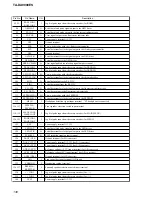
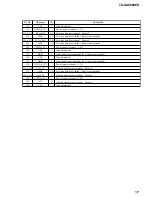
TA-DA9000ES
Pin No.
Pin Name
I/O
Description
111
VSS
—
Ground terminal
112
DVDD (3.3V)
—
Power supply terminal (+3.3V)
113 to 119
D6 to D12
I/O
Two-way data bus terminal Not used
120
HD4
I/O
Two-way data bus with the i. link system controller
121 to 123
D13 to D15
I/O
Two-way data bus terminal Not used
124
HD5
I/O
Two-way data bus with the i. link system controller
125
CVDD (1.8V)
—
Power supply terminal (+1.8V)
126
VSS
—
Ground terminal
127
HDS1
I
Data strobe signal input from the i. link system controller
128
VSS
—
Ground terminal
129
HDS2
I
Data strobe signal input from the i. link system controller
130
DVDD (3.3V)
—
Power supply terminal (+3.3V)
131 to 134
A0 to A3
O
Address signal output terminal Not used
135
HD6
I/O
Two-way data bus with the i. link system controller
136 to 141
A4 to A9
O
Address signal output terminal Not used
142
CVDD (1.8V)
—
Power supply terminal (+1.8V)
143
A21
O
Address signal output terminal Not used
144
VSS
—
Ground terminal
Содержание TA-DA9000ES
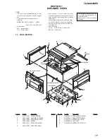
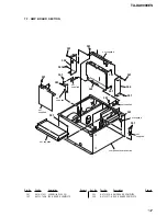
Страница 16: ...16 TA DA9000ES 3 10 MOTHER BOARD 1 four screws transistor 3 mother board 2 heat sink ...
Страница 22: ...MEMO TA DA9000ES 22 ...
Страница 193: ...193 TA DA9000ES MEMO ...