background image

7-3

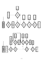
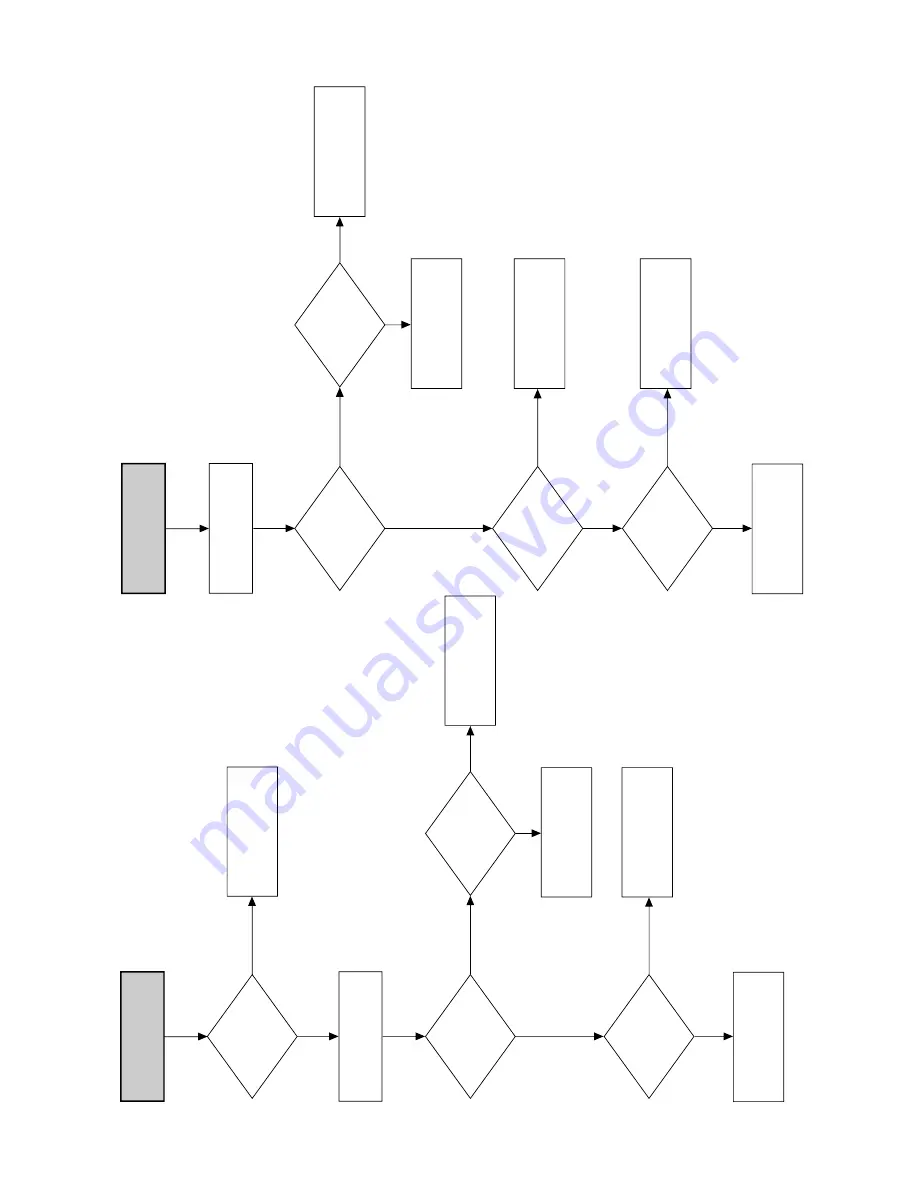
RECORD MODE 

DOESN'T OPERATE

PLAY

OPERATION

LOAD VCR WITH A

BLANK TAPE AND

PRESS RECORD BUTTON

REC MODE

SAFETY TAB

SEE 

(AUDIO MISSING IN 

RECORD MODE)

CHANGE SW602 (REC SW)

CHANGE TAPE

SEE

(PLAY MODE

DOESN'T OPERATE)

EJECT

NO

NO

YES

REC-VIDEO

SEE 

(VIDEO MISSING IN 

RECORD MODE)

NO

YES

YES

YES

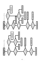
(VCR Section)

LOAD TAPE AND

PRESS F.FWD BUTTON

FAST FORWARD

DOESN'T OPERATE

F.FWD

INDICATOR IN 

THE DISPLAY

PRESS FF 

KEY IN REMOTE 

CONTROL

MECHANISM

STATE

IC601-76, 77, 78

CHECK

MECHANISM

CHECK TIMER

CHANGE IC601-58

NO

NO

YES

STOP

CAPSTAN MOTOR

ROTATION

SEE 

(CAPSTAN DOES NOT

ROTATE)

SEE 

(MECHANISM DOES NOT

OPERATE IN PLAY MODE)

STOP

YES

F.FWD

ROTATE

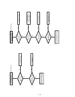
(VCR Section)

Содержание SLV-D900E

Страница 1: ...CAL or COAXIAL jack are converted to 48 kHz sampling frequency Inputs and outputs LINE 1 EURO AV 21 pin Video input pin 20 Audio input pins 2 and 6 Video output pin 19 Audio output pins 1 and 3 LINE 3 21 pin Video input pin 20 Audio input pins 2 and 6 LINE 2 IN t o L R VIDEO IN phono jack 1 Input signal 1 Vp p 75 ohms unbalanced sync negative AUDIO IN phono jack 2 Input level 327 mVrms Input imped...

Страница 2: ...r correcting the original service problem perform the following safety checks before releasing the set to the customer This appliance is classified as a CLASS 1 LASER product The CLASS 1 LASER PRODUCT MARKING is located on the rear exterior 4 Look for parts which though functioning show obvious signs of deterioration Point them out to the customer and recommend their replacement 5 Check the B volt...

Страница 3: ...ram 3 1 4 PCB Diagrams 4 1 VCR Main 4 3 4 2 DVD Main 4 7 4 3 Function Timer 4 9 5 Schematic Diagrams Block Identification of Main PCB 5 3 5 1 S M P S 5 5 5 2 Power Drive 5 7 5 3 OSD VPS PDS 5 9 5 4 NICAM 5 11 5 5 A V 5 13 5 6 Hi Fi 5 15 5 7 Input Output 5 17 5 8 TM 5 19 5 9 Syscon 5 21 5 10 DVD Main Micom AV Decoder 5 23 5 11 DVD Servo 5 25 5 12 DVD Audio Video 5 27 6 VCR Alignment and Adjustments...

Страница 4: ... gives them the same ground as the sheet 4 Remove the optical pick up block 5 Perform work on top of the conductive sheet Be careful not to let your clothes or any other static sources to touch the unit Be sure to put on a wrist strap grounded to the sheet Be sure to lay a conductive sheet made of copper etc Which is grounded to the table 6 Short the short terminal on the PCB which is in side the ...

Страница 5: ...der land 2 points short on Pick up See Fig 2 4 Disassembly the Pick up 2 2 Assembly 1 Replace the Pick up 2 Remove the soldering 2 points on Pick up 3 Reassemble the Deck Assy Note If the assembly and disassembly are not done in correct sequence the Pick up may be damaged SOLDER LAND 2 POINTS SHORT PICK UP ASS Y Fig 2 ...

Страница 6: ...nufacturer s code number Now you can use the 1 VOL PROG MUTING TV VIDEO 0 9 and buttons to control your TV You can also use the buttons marked with a dot to control a Sony TV To control the DVD VCR reset TV DVD VIDEO to DVD VIDEO for Sony TV only Code numbers of controllable TVs If more than one code number is listed try entering them one at a time until you find the one that works with your TV No...

Страница 7: ...omatically 1 Turn on your TV and set it to the video channel If your TV does not have a Scart EURO AV connector tune the TV to channel 21 the initial RF channel for this DVD VCR Refer to your TV manual for TV tuning instructions If the picture does not appear clearly see To change the RF channel on page 15 2 Connect the mains lead to the mains The DVD VCR automatically turns on and the DVD VCR sta...

Страница 8: ...d 18 Setting the clock Tips If you set AUTO CLOCK to ON the Auto Clock Set function is activated whenever the DVD VCR is turned off The time is adjusted automatically by making reference to the time signal from the station To change the digits while setting press B to return to the item to be changed and select the digits by pressing V v 4 Press b to select the minutes and set the minutes by press...

Страница 9: ...ons Before you start Turn on the DVD VCR and your TV Set your TV to the video channel so that the signal from the player appears on the TV screen If the DVD player is in play mode you cannot display the SETUP MENU Stop DVD playback RETURN SET UP O RETURN V v B b ENTER continued 22 Presetting channels 1 Press SET UP The SETUP MENU appears 2 Press V v B b to select INSTALLATION then press ENTER The ...

Страница 10: ...URN SET UP DVD SETUP RETURN SETUP MENU Vv b B ENTER ENTER RETURN MANUAL SET UP AUTO SET UP VIDEO OUTPUT CH CH21 INSTALLATION ENTER vV continued 26 Presetting channels 3 Press V v to select MANUAL SET UP then press ENTER 4 Press V v to select the row which you want to change or enter the station name then press b To display other pages for programme positions 6 to 80 press v V repeatedly 5 Press V ...

Страница 11: ...o component having a built in DTS decoder The DVD player outputs the DTS signal via the DIGITAL AUDIO OUT COAXIAL or OPTICAL jack even if DTS is set to Off in AUDIO SETUP menu page 53 and may affect your ears or cause your speakers to be damaged Notes on playing DVDs with a DTS sound track DTS audio signals are output only through the DIGITAL AUDIO OUT COAXIAL or OPTICAL jack When you play a DVD w...

Страница 12: ...ape The picture becomes black and white The picture shakes No picture appears on the TV screen Black streaks appear horizontally on the TV screen The colour density increases or decreases When 10 hours have passed the counter in the display window returns to 0 00 00 and the count starts over again The sound is muted during playback at various speeds The picture may show noise when playing at high ...

Страница 13: ...us system Recording TV programmes using the VIDEO Plus system The VIDEO Plus system is the feature that simplifies programming the VCR to make timer recordings Just enter the PlusCode number listed in the TV programme guide The date times and programme position of that programme are set automatically You can preset a total of eight programmes including settings made with other timer methods Before...

Страница 14: ...s automatically changed to the LP mode Note that some noise will appear on the picture when the tape speed is changed To operate this function correctly the Tape Select setting in the VIDEO FUNCTION SETUP menu must be accurate see page 90 1 Turn on the satellite tuner 2 On the satellite tuner select the satellite programme for which you want to make a timer setting 3 Keep the satellite tuner turne...

Страница 15: ...g in the VIDEO FUNCTION SETUP menu must be accurate see page 90 Tips To set the line input video source you can also use the INPUT SELECT button Even if you set TIMER METHOD to VIDEOPLUS in the USER SET menu you can set the timer manually Press SET UP to select TIMER PROGRAMMING then go to step 2 To check change or cancel the programme setting see Checking changing cancelling timer settings on pag...

Страница 16: ...kers to audio input white red to LINE OUT L R AUDIO continued 50 A V Receiver hookup B Use this hookup if your A V receiver has a Dolby Digital MPEG audio or DTS decoder a digital input jack and 6 speakers This connection will allow you to use the Dolby Digital MPEG audio or DTS decoder function of your AV amplifier receiver You are not able to enjoy the surround sound effects of this player You m...

Страница 17: ...y Digital decoder Off Select this when the player is connected to an audio component lacking a built in DTS decoder On Select this when the player is connected to an audio component with a built in DTS decoder Standard Normally select this position TV Mode Makes the low sounds clear even if you turn the volume down ENTER ENTER RETURN RETURN continued 54 Audio Setup MPEG Selects the type of MPEG au...

Страница 18: ...ears 2 Press V v B b to select DVD SETUP then press ENTER The DVD SETUP menu appears 3 Press V v to select the language setup item from the displayed list DVD Menu Audio or Subtitle Then press ENTER V v B b ENTER SET UP O RETURN SET UP DVD SETUP RETURN SETUP MENU Vv b B ENTER ENTER DVD Menu Subtitle Audio Setup Screen Setup Parental Audio English Audio Follow Unlocked Original RETURN DVD SETUP ENT...

Страница 19: ...you play DVDs which do not have the Parental Control function playback cannot be limited on this player All the ratings higher than the level you select will be blocked Write your password down and keep it in a safe place in case you forget it 6 Press V v to select the level you want then press ENTER The options are as follows Level 8 Adult y Level 7 y Level 6 y Level 5 y Level 4 y Level 3 y Level...

Страница 20: ...VD appears in the display when you press ANGLE during playback This means that you can change the viewing angle 1 Press ANGLE during playback The angle number appears on the display The number after the slash indicates the total number of angles 2 Press V v repeatedly to select the angle number The scene changes to the selected angle ANGLE V v ANGLE SQPB 1 6 v V ENTER 67 Displaying the subtitle DV...

Страница 21: ...CLEAR PROGRAM continued 70 Various play mode functions Programme play Random play Repeat play To stop programme play Press CLEAR during programme play To change or cancel a programme 1 Press PROGRAM when the DVD player is in stop mode 2 Press B b to select PROGRAM then press ENTER 3 Press V v B b to select the chapter track number you want to programme then press ENTER You can also use the number ...

Страница 22: ...D AUDIO SUBTITLE LANGUAGE on page 109 for the abbreviation of the language When playing a VIDEO CD CD or DATA CD MP3 audio The default setting is indicated in bold print AUDIO V v AUDIO ENG DOLBY DIGITAL 5 1CH v V ENTER STEREO The standard stereo sound Left The sound of the left channel monaural Right The sound of the right channel monaural 74 Virtual surround setting Virtual surround setting To c...

Страница 23: ...me to start 3 To change the album press O RETURN 4 Press V v to select an album then press ENTER The list of tracks contained in the album appears To select a track repeat step 2 RETURN MP3 album 1 2 album 2 3 album 3 track 1 v V 1 album 1 ENTER MP3 album 1 2 track 2 3 track 3 4 track 4 5 track 5 6 track 6 7 track 7 8 track 8 track 1 v V 1 track 1 Total 012 continued 78 Playing an MP3 audio track ...

Страница 24: ...s recorded in EP Extended Play mode on an NTSC system is not guaranteed The SQPB Super VHS Quasi Playback function is only for playing a Super VHS format tape 1 Insert a Super VHS format tape 2 Press H 3 Press SQPB to start SQPB SQPB H ANGLE SQPB 82 Setting the recording duration time Setting the recording duration time After you have started recording you can have the VCR stop recording automatic...

Страница 25: ...the picture Monaural sound is recorded onto the normal audio track along the edge of the tape Notes To listen to playback sounds in stereo you must use the Scart or AUDIO OUT connections When you play a tape recorded in monaural the sound is heard in monaural regardless of the AUDIO setting Stereo Usually mixed left right channels Bilingual Usually main sound Normal audio track monaural Hi fi audi...

Страница 26: ... the original screen ENTER USER SET COLOUR SYSTEM SMART TRILOGIC AUTO POWER OFF OFF VIDEOPLUS EXTEND NICAM ON AUTO ON OFF TIMER METHOD VARIABLE RETURN vV B b ENTER SMART TRILOGIC ON ON OFF PICTURE SOFTEN SHARPEN RETURN vV B b RETURN 90 Changing menu options Changing menu options 1 Press SET UP when the DVD player is in stop mode 2 Press V v B b to select Video Function Setup then press ENTER The V...

Страница 27: ...art editing Turn on your TV and set it to the video channel Press INPUT SELECT to display the connected line in the display window Press SP LP to select the tape speed SP or LP Press SELECT VIDEO to control the VCR TV LINE 3 VMC 2121HG Scart cable not supplied Scart EURO AV Signal flow Your VCR Recorder Other VCR Player z REC X continued 94 Editing To stop editing Press the x buttons on both VCRs ...

Страница 28: ...rough the DIGITAL AUDIO OUT OPTICAL or COAXIAL jack check the audio settings pages 49 50 Sound is noisy When playing a CD with DTS sound tracks noise will come from the LINE OUT L R AUDIO jacks page 29 or DIGITAL OUT OPTICAL or COAXIAL jack The sound volume is low The sound volume is low on some DVDs The sound volume may improve if you set Audio DRC to TV Mode page 53 Operation The disc does not p...

Страница 29: ...RAMMING menu does not appear Check that TIMER METHOD in the USER SET menu is set correctly page 95 The PDC function does not operate properly Check that the clock and the date are set correctly Check that the PDC time you set is the correct one there might be a mistake in the TV programme guide If the broadcast you wanted to record did not send the good PDC information the VCR will not start recor...

Страница 30: ...nder for VCR A TV DVD VIDEO switch 9 B Z eject button 32 C SELECT VIDEO button 9 D Number buttons 1 10 E CLEAR button 24 F SET UP button 15 G TIMER button 44 H AUDIO 1 button 84 I INDEX button 86 J C STEP button 32 K z REC record button 35 L X pause button 32 M H play button 1 31 N V v B b buttons ENTER button 14 O DISPLAY button 35 P 1 on standby switch 10 32 Q PROG programme TRACKING buttons 2 3...

Страница 31: ...net Top Removal 2 1 2 Bottom Cover Removal 2 1 3 Ass y Front Panel Removal Fig 2 4 Function Timer PCB Removal Fig 2 3 Ass y Front Panel Removal 2 1 4 Function Timer PCB Removal Lift up the Cabinet Top in the direction of arrow 1 REMOVE 3 SCREWS 1 REMOVE 3 SCREWS 1 RELEASE 4 HOOKS 2 RELEASE 3 HOOKS Top View Bottom View 1 RELEASE 4 HOOKS ...

Страница 32: ... 2 6 VCR Main PCB Removal 4 REMOVE 3 SCREWS 2 REMOVE 2 SCREWS 3 REMOVE 2 SCREWS 1 REMOVE CONNECTORS DVD MAIN PCB DVD DECK VCR MAIN PCB 1 REMOVE 3 SCREWS MODE SWITCH When installing the ass y full deck on the Main PCB be sure to align the assembly point of mode switch ASSEMBLY POINT ...

Страница 33: ...lider Housing 3 in the direction arrow A 2 When the Tray Disc 4 comes out a little pull it in the direction arrow B by hand 3 Pull the Tray Disc 4 to disassemble while simultaneously pushing 2 Stoppers 5 left right in the direction arrow C D A 1 SCREW DRIVER 2 EMERGENCY HOLE 3 SLIDER HOUSING 4 TRAY DISC B C 5 STOPPER 5 STOPPER D ...

Страница 34: ...Disconnect DCN2 1 DCN2 2 2 Lift down the Assy P U Deck 3 while simultaneously pushing 2 Hooks 4 5 in the direction of arrow A B Fig 2 8 Ass y P U Deck Removal 1 DCN2 5 HOOK 4 HOOK 2 DCN3 3 ASSY P U DECK A B Assembly Point SLIDER HOUSING ...

Страница 35: ...using 5 5 Remove the soldering 6 of 2 points Red Black 6 Remove 2 Screws 7 and lift down the Motor Load Assy 8 7 Push the 2 Hooks 9 bottom side in the direction arrow C and lift up the Housing PCB 0 8 Push the Hooks qa and remove Deck PCB qs Fig 2 9 Housing Ass y Removal 1 BELT 3 PULLEY GEAR 4 GEAR TRAY 8 MOTOR LOAD ASSY 9 3 HOOKS 0 HOUSING PCB qa HOOK 6 SOLDERING 7 2 SCREWS 5 SLIDER HOUSING 2 HOO...

Страница 36: ...4 Sub Chassis Removal 1 Remove the Soldering of Motor Feed wire 1 2 Remove the 4 Screws 2 3 Lift up the Ass y Brkt Deck 3 Fig 2 10 Sub Chassis Removal 2 4 SCREWS 3 ASSY BRKT DECK 1 SOLDERING OF MOTOR FEED WIRE ...

Страница 37: ...s 4 4 Remove Shaft Pick Up 5 and Pick Up Assy 6 5 Remove 1 Screw 7 6 Remove 2 Screws 8 7 Remove 2 Spring Spindle 9 and Motor Spindle Ass y 0 Fig 2 11 Ass y Brkt Deck Removal 4 2 SCREW 1 WASHER 2 GEAR FEED B 8 2 SCREWS 7 1 SCREW 5 SHAFT PICK UP 3 GEAR FEED A 6 PICK UP ASS Y 9 SPRING SPINDLE 0 MOTOR SPINDLE ...

Страница 38: ...2 8E Fig 2 12 Circuit Board Locations 2 3 Circuit Board Locations VCR MAIN PCB DVD MAIN PCB FUNCTION TIMER PCB ...

Страница 39: ...3 Block Diagram 3 2E 3 1 SLV D900E D900G ...

Страница 40: ...4 PCB Diagrams 4 1 VCR Main 4 3 4 2 DVD Main 4 7 4 3 Function Timer 4 9 4 2 4 1 SLV D900E D900G ...

Страница 41: ...4 3 4 4 4 1 VCR Main COMPONENT SIDE ...

Страница 42: ...4 6 4 5 CONDUCTOR SIDE ...

Страница 43: ...4 7 4 8 4 2 DVD Main CONDUCTOR SIDE COMPONENT SIDE ...

Страница 44: ...4 10E 4 9 4 3 FUNCTION Timer COMPONENT SIDE CONDUCTOR SIDE ...

Страница 45: ... 5 7 5 3 OSD VPS PDS 5 9 5 4 NICAM 5 11 5 5 A V 5 13 5 6 Hi Fi 5 15 5 7 Input Output 5 17 5 8 TM 5 19 5 9 Syscon 5 21 5 10 DVD Main Micom AV Decoder 5 23 5 11 DVD Servo 5 25 5 12 DVD Audio Video 5 27 5 Schematic Diagrams SLV D900E D900G DVD Main PCB VCR Main PCB 5 2 5 1 ...

Страница 46: ...5 4 5 3 Component Side Conductor Side VCR MAIN PCB Component Side DVD MAIN PCB Block Identification of Main PCB ...

Страница 47: ...5 6 5 5 5 1 S M P S ...

Страница 48: ...5 8 5 7 FROM TO DVD Audio Video CN4 5 2 Power Drive ...

Страница 49: ...5 10 5 9 5 3 OSD VPS PDS ...

Страница 50: ...5 12 5 11 5 4 NICAM ...

Страница 51: ...5 14 5 13 5 5 A V ...

Страница 52: ...5 16 5 15 5 6 Hi Fi ...

Страница 53: ...5 18 5 17 5 7 Input Output ...

Страница 54: ...5 20 5 19 5 8 TM ...

Страница 55: ...5 22 5 21 5 9 SYSCON ...

Страница 56: ...5 24 5 23 5 10 DVD Main Micom AV Decoder ...

Страница 57: ...5 26 5 25 5 11 DVD Servo ...

Страница 58: ...5 28E 5 27 5 12 DVD Audio Video ...

Страница 59: ...ment 3 When replacing the cylinder ass y be sure to adjust the X Point and Head switching adjustment 4 How to adjustment Press the TEST botton on Main PCB Function PCB to set the adjustment mode If the corresponding adjustment botton is pressed the adjustment is performed automatically If the adjustment is completed be sure to turn the power off 6 1 1 Location of adjustment button of remote contro...

Страница 60: ...6 2 6 1 2 TEST location for adjustment mode setting TEST SW709 BUTTON Fig 6 2 Function Timer PCB Top View ...

Страница 61: ... PCB Top View 6 2 2 ACE Head position X Point Adjustment See the 2 2 1 d ACE Head Position X Point Adjustment on page 2 2 of the Mechanical Manual 1 Playback the alignment tape Color bar 2 Press the TEST botton on F Timer PCB to set the adjustment mode See Fig 6 2 3 Press the 5 button of remote control then adjustment is operated automatically See Fig 6 1 4 Connect the CH 1 probe to W569 Envelope ...

Страница 62: ...If selecting the option number is completed press the ENTER button of remote control If ENTER button is pressed the selected number is changes reversed color See Fig 6 4 5 Press the RETURN button of remote control again to store the option number PLEASE WAIT is displayed for a second as shown Fig 6 5 and this setting is completed 6 Turn the Power off 01 02 03 04 05 06 07 08 09 10 11 12 13 14 15 16...

Страница 63: ...ector Wafer AL5V IC701 5 20 No Data IN OUT CLK IC701 2 3 4 Yes No No Yes VCR Section EE VIDEO Insert the cassette tape recorded by another VCR and press PLAY Button See Video Missing in EE Mode Yes Play Indicator in the display Yes Yes No Mechanism operation See Mechanism doesn t operate in play mode Yes No PB VIDEO See Video missing in play mode See PB VIDEO audio mising in play mode Yes No Press...

Страница 64: ... PG IC601 97 SEE IC601 9 CYLINDER DOES NOT ROTATE CHECK START END SENSOR S601 S602 IC601 NO NO NO NO LOW YES YES HIGH YES YES CHECK TAPE AND END SENSOR CHECK LM B AND LM VCR Section A CAPSTAN ROTATION S T REEL IC601 98 99 PROG SW STATE IC601 76 77 78 CHANGE IC601 CHECK LOADING MOTOR MECHANISM OR SW601 TAKE UP REEL SENSOR SUPPLY REEL SENSOR PT601 PT602 SEE CAPSTAN DOES NOT ROTATE NO DC STOP MODE YE...

Страница 65: ...O NO YES REC VIDEO SEE VIDEO MISSING IN RECORD MODE NO YES YES YES VCR Section LOAD TAPE AND PRESS F FWD BUTTON FAST FORWARD DOESN T OPERATE F FWD INDICATOR IN THE DISPLAY PRESS FF KEY IN REMOTE CONTROL MECHANISM STATE IC601 76 77 78 CHECK MECHANISM CHECK TIMER CHANGE IC601 58 NO NO YES STOP CAPSTAN MOTOR ROTATION SEE CAPSTAN DOES NOT ROTATE SEE MECHANISM DOES NOT OPERATE IN PLAY MODE STOP YES F F...

Страница 66: ... NO NO YES STOP DOES CAPSTAN MOTOR ROTATE CHECK IC601 25 CM F R SEE MECHANISM DOES NOT OPERATE IN PLAY MODE NO YES YES REW YES VCR Section FWD SEARCH DOESN T OPERATE PLAY OPERATION PRESS F FWD FOR FORWARD SEARCH CHECK IC601 CHECK CAPSTAN MOTOR IS CAPSTAN SPEED CHANGED SEARCH OPERATION NOISE BAR LOCKING END ADJUST A CE HEAD CHANGE DECK CHANGE IC601 SEE PLAY DOESN T OPERATE NO NO NO YES NO CONTROL P...

Страница 67: ...AMP ENV COMP CHECK CAPSTAN MOTOR NOISE BAR LOCKING ADJUST A CE HEAD NO CONTROL PULSE IC601 89 NO YES YES YES VCR Section TURN THE VCR POWER ON AND INSERT A TAPE PRESS EJECT BUTTON CASSETTE LOADING MECHANISM DOES NOT OPERATE TAPE DETECTED CST IN MODE IC601 74 HIGH 5V IC601 75 LOW 0V CHANGE IC601 CHECK START END SENSOR IC601 CHECK DM B LINE CHANGE CAPSTAN MOTOR NO NO NO YES IC601 39 5V IC601 38 0V I...

Страница 68: ...DEO SIGNAL IC301 50 CHECK TM401 ANTENNA IN CHECK IC801 3 TO TM401 24 LINE NO VIDEO SIGNAL TM401 24 CHECK IIC CLK DATA LINE CHECK IC301 NO IIC CLK DATA IC301 68 69 VCR Section VIDEO MISSING IN RECORD MODE PLACE THE VCR RECORD MODE VIDEO EE MODE OPERATION VIDEO SIGNAL IC301 48 50 52 VIDEO SIGNAL IC801 4 CHECK VIDEO HEAD CHECK IC801 C804 C805 SEE VIDEO MISSING IN EE MODE NO NO NO NO NO NO YES YES YES...

Страница 69: ...ES NO YES YES YES VIDEO FM IC301 21 VIDEO SIGNAL IC301 78 VIDEO SIGNAL IC301 65 VIDEO SIGNAL IC6P01 19 VIDEO SIGNAL IC301 61 NO H D SW IC301 70 NO YES YES YES NO NO NO CHECK C380 VCR Section COLOR MISSING IN RECORD MODE VIDEO IN RECORD MODE COLOR SIGNAL IC301 58 COLOR KILLER IC301 33 2V CHANGE IC301 CHANGE IC301 CHECK THE REC LINE CHANGE XT301 CHECK XT301 SEE PAGE 7 6 VIDEO MISSING IN RECORD MODE ...

Страница 70: ...RY IC301 70 CHANGE IC301 CHECK IC301 27 34 XT301 CHECK IC601 29 SEE PAGE 7 7 VIDEO MISSING IN PLAY MODE NO NO NO YES YES NO YES VCR Section CHECK IC301 61 OSD PICTURE MISSING CHECK IC301 65 CHECK IC6P01 19 CHANGE IC6P01 CHECK IC6P01 9 10 11 SEE PAGE 7 7 VIDEO MISSING IN PLAY MODE NO NO YES NO VCR Section ...

Страница 71: ...DGE VIDEO SIGNAL IC6P01 19 NO CHECK OSD VIDEO IN LINE YES YES NO VCR Section CHECK AUDIO MISSING IN EE MODE PLACE IN PB MODE AUDIO MISSING IN PB MODE CHANGE IC501 YES IC501 78 80 NO AUDIO SELECT CHECK C3A16 MONO HI FI IC301 5 AUDIO SIGNAL NO YES CHECK C3A17 AND CHANGE IC301 IC301 6 DC 2 3V YES NO VCR Section CHECK ACE HEAD R3A07 R3A08 R3A06 C3A15 AND CHANGE IC301 CHECK IC501 40 39 38 H D SW EC CLK...

Страница 72: ...01 38 39 CLK DATA NO YES VCR Section CHECK Q3A03 Q3A02 CHECK R3A04 CHECK R373 IC301 15 AUDIO SIGNAL IC501 4 AUDIO SIGNAL NO NO NO CHECK IC301 68 69 CLOCK DATA CHECK C523 R512 R511 NO NO YES NO YES YES YES YES YES YES CHECK IC301 14 C3A02 IC301 12 AND CHANGE IC301 CHANGE IC501 IC301 11 AUDIO SIGNAL IC301 100 AUDIO SIGNAL IC301 5 MIX SIGNAL AUDIO 70KHz CN3A01 4 OSCILLATION NO CHECK AUDIO MISSING IN ...

Страница 73: ...NO TUNER YES IC501 78 80 AUDIO SIGNAL NO YES CHECK IC601 IC501 38 39 CLK DATA NO YES VCR Section CAPSTAN DOES NOT ROTATE PLACE THE VCR IN PLAY MODE CN604 2 24V CN604 3 PC 5V CN604 9 CN604 5 CN601 3 OUTPUT PWM IC601 10 CAP M CTL CHECK CAPSTAN MOTOR CHECK R660 C691 CHECK R609 R685 C623 CHANGE IC601 CHECK IC601 CHECK B IN THE POWER BLOCK CHECK 5 8V AT PC5 8V LINE IN THE POWER BLOCK NO NO NO NO YES NO...

Страница 74: ...TATE PLACE THE VCR IN PLAY MODE IC604 8 12V CYL SPEED XT602 18 19 8MHZ CHECK CYLINDER MOTOR CHANGE XT601 C626 C627 CHECK D PG D FG IC601 97 CHECK 12V AT PC12V LINE IN THE POWER BLOCK NO FASTER NO YES SLOWER YES VCR Section ...

Страница 75: ... key input No focus incoming and no disc occurs Yes No D C DVD Section No focus incoming FE in SIC1 25 is within specified range DRIC1 26 27 output are normal Check open state from DRIC1 to pick up Check RIC1 and A B C D input Check DRIC1 Yes Yes No No C DVD Section ...

Страница 76: ...MIC1 Yes No SLED SLED DRICI 32 33 output are normal Check DRIC1 Yes No DVD Section NO LD CD ON RIC1 21 is 5V Current exceeds 0 1A LD out pick up replace Open check in related circuit Check MIC1 Yes Yes Yes No No Divide RQ5 emitter terminal voltage and 5V real voltage difference into 10ohm D DVD Section ...

Страница 77: ...ne Seek Check No Yes Check pick up No DVD Section FINE SEEK Check FINE SEEK MIRR signal RIC1 46 is missing TZCO signal SIC1 24 is occurs Track incomming is delayed TE is within 2V and 3V Pick up transfer smooth Check RIC1 Peripheral curcuit Check SIC1 Peripheral curcuit Time out due to many jump counts Check SIC1 peripheral circuit SIC1 33 output is normal DRIC1 28 29 terminal outputs are normal C...

Страница 78: ...C D Yes Yes Yes Yes Yes Yes No No No No No No DVD Section CD Play Abnormal rotation of disc motor Input of RF signal is normal PRICI 4 EFMO PLCK Input is normal SIC1 97 92 SPD output is normal SIC1 35 After resoldering SIC1 DRIC1 2 output FG is normal DRIC1 10 signal MON is H Check or replace disc motor Check SIC1 MIC1 Check DRIC1 soldering and power Check path to RIC1 and SIC1 Check RIC1 solderin...

Страница 79: ...tion CD VCD DVD L R output error Mixed Audio output Normal DATA 0 is input in AIC2 2 Analog output of AIC2 7 8 is normal Check JACK1 JK801 Audio out peripheral soldering shot IC801 Check ZIC1 121 output Check ZIC1 125 CD VCD 16 9344MHz DVD 18 432MHz Yes Yes No No AIC4 1 7 output is normal Check AIC4 peripheral circuit Yes No Base terminal level of AQ3 AQ6 are L Check IC601 50 mute Yes No DVD Secti...

Страница 80: ...ck JACK1 DOIC2 peripheral soldering shot Check ZIC1 peripheral circuit Check DOIC1 Yes No No Yes DVD Section S Video output error DVD SETUP in OSD Alt video is Component VIC1 2 4 6 signal MM1567 Change the Alt video mode to S Video Check VIC1 No Yes Yes Check ZIC1 ZIVA4 1 No Yes E DVD Section ...

Страница 81: ...1 Check the connection between pin 6 in XIC1 and pin 129 in ZIC1 Check the soldering of ZIC1 Yes No No Analog signals are inputted normally pin 26 in CN01 VCR MAIN PCB Yes No Analog signals are inputted pin 13 in IC801 Yes No Yes Check the connection between pin 133 in ZIC1 DVD MAIN PCB and CN01 VCR MAIN PCB Check L804 C828 C827 No Check the IC801 Pin of VDD_2 5 VDD 3 3 in Zic1 has normal level Ch...

Страница 82: ...ts List 8 1 Exploded Views 8 1 1 Cabinet Assembly 8 1 2 VCR Mechanical Parts Top Side 8 1 3 VCR Mechanical Parts Bottom Side 8 1 4 DVD Mechanical Parts 8 2 Electrical Parts List 8 2 8 2 8 3 8 4 8 5 8 6 SLV D900E D900G ...

Страница 83: ... DOOR TRAY 4 3 080 529 01 DOOR CASSETTE COMBO EURO 5 3 080 528 01 SPRING ETC 6 1 817 010 11 CONNECTOR HEADER 7 3 080 527 01 LEG ORNAMENT 010 1 823 023 11 POWER CORD KKP419C D900E 010 1 823 025 11 POWER CORD Y352 D900G 11 3 080 521 01 CABINET TOP COMBO EURO 12 3 075 256 01 SCREW TAP 3X12 13 3 075 262 01 SCREW BH 4X12 14 3 078 566 01 SCREW TAP M3 L10 BLK 15 1 477 772 11 COMMANDER STANDARD RMT V503 1...

Страница 84: ...hanical Parts Top Side 112 3 067 784 01 LEVER UNIT PINCH 113 3 075 257 01 SCREW TAP 2 6X5 114 3 080 611 01 ASSY ACE HEAD 115 3 067 789 01 GUIDE CASS DOOR 118 1 763 836 11 LOADING ASSY MOTOR 120 3 067 787 01 LEVER FL DOOR 121 3 067 796 01 PLATE GROUND DECK 123 3 075 046 01 DISK T REEL 124 3 075 047 01 DISK S REEL 126 3 080 650 01 SLEEVE HEAD CLEANER 127 3 080 651 01 LEVER HEAD CLEANER ASSY 109 111 ...

Страница 85: ...t supplied not supplied not supplied not supplied not supplied not supplied 151 152 154 153 151 3 067 790 01 BELT PULLEY 152 1 763 835 11 MOTOR CAPSTAN Ref No Part No Description Remarks Ref No Part No Description Remarks 153 3 075 259 01 SCREW CAP 2 6X6 154 3 075 260 01 SCREW MAC 3X3 ...

Страница 86: ... UP 205 3 078 588 01 SHAFT PU 206 1 796 536 11 ASSY MOTOR SPINDLE 207 3 078 597 01 SPRING ETC SPINDOLE CHASSIS SUB 208 3 078 592 01 SCREW TAP 2X6 209 3 078 596 01 RUBBER INSULATOR 210 1 796 537 11 FEED ASSY MOTOR 211 3 078 589 01 GEAR FEED A 212 3 078 590 01 GEAR FEED B 213 3 078 591 01 WASHER SLIT 214 3 078 587 01 SCREW MAC 2 6X7 215 3 078 593 01 SCREW SPE SWRCH18A 216 3 078 594 01 SCREW MAC 2X6 ...

Страница 87: ...805 019 11 IC CMOS LOGIC 7ST08 PIC1 1 805 030 11 IC V REGULATOR 1563 PIC2 1 805 032 11 IC V REGULATOR MM1561 PIC3 1 805 031 11 IC V REGULATOR 3RD13 PRIC1 1 805 040 11 IC ASIC S5LR010X01 PRIC2 1 805 022 11 IC CMOS LOGIC 74VHCT125A RIC1 1 805 038 11 IC ASIC KS1462B SIC1 1 805 037 11 IC ASIC KS1454 SIC2 1 805 033 11 IC DRAM 416C256 SIC4 1 805 019 11 IC CMOS LOGIC 7ST08 VIC1 1 805 029 11 IC VIDEO AMP ...

Страница 88: ...NDUCTOR 0uH BD1SS2 1 400 085 11 INDUCTOR 0uH BD1SS3 1 400 085 11 INDUCTOR 0uH BD1SS4 1 400 085 11 INDUCTOR 0uH 0L1SS01 1 424 830 11 LINE FILTER 30mH 0L1SS02 1 456 315 11 LINE FILTER 400uH L1SS03 1 424 828 11 COIL CHOKE 10uH L1SS04 1 424 828 11 COIL CHOKE 10uH L1SS05 1 424 828 11 COIL CHOKE 10uH L814 1 400 085 11 INDUCTOR 0uH CAPACITOR 0C1SS01 1 165 573 11 CONDENSER FILM 0 1uF 0C1SS02 1 165 573 11 ...

Страница 89: ... AV LINE 3 PHOTO INTERRUPTER PT601 1 804 770 11 TRANSISTOR PHOTO INTERRUPTER PT602 1 804 770 11 TRANSISTOR PHOTO INTERRUPTER TRANSFORMER 0PT1S01 1 439 633 11 TRANS SWITCHING EER3530 TRANSISTOR Q1P101 1 804 424 11 TRANSISTOR KSC2328AY Q1P102 1 804 429 11 TRANSISTOR KSR2001 Q1P103 1 804 421 11 TRANSISTOR KSC945 Q1P104 1 804 424 11 TRANSISTOR KSC2328AY Q1P105 1 804 424 11 TRANSISTOR KSC2328AY Q1P106 ...

Страница 90: ...96 620 11 ASSY PICK UP 206 1 796 536 11 ASSY MOTOR SPINDLE 210 1 796 537 11 FEED ASSY MOTOR 218 1 761 641 11 ASSY DVD DECK DP 7S COMBO P P P P P P P P P P P P P P P P P P P P P P P P P P P P P P P P ACCESSORIES PACKING MATERIALS 1 477 772 11 COMMANDER STANDARD RMT V503 3 079 775 11 MANUAL INSTRUCTION ENGLISH D900G 3 079 775 21 MANUAL INSTRUCTION FRENCH D900E 3 079 775 31 MANUAL INSTRUCTION SPANISH...

Страница 91: ... 118 Sony Corporation Home Video Company 9 929 738 11 2002K0500 1 2002 11 Published by Quality Assurance Dept SLV D900E D900G ...

Отзывы: