1-22
92
Editing
Editing
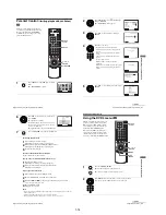
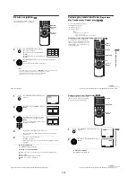
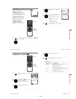
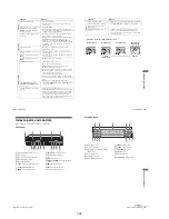
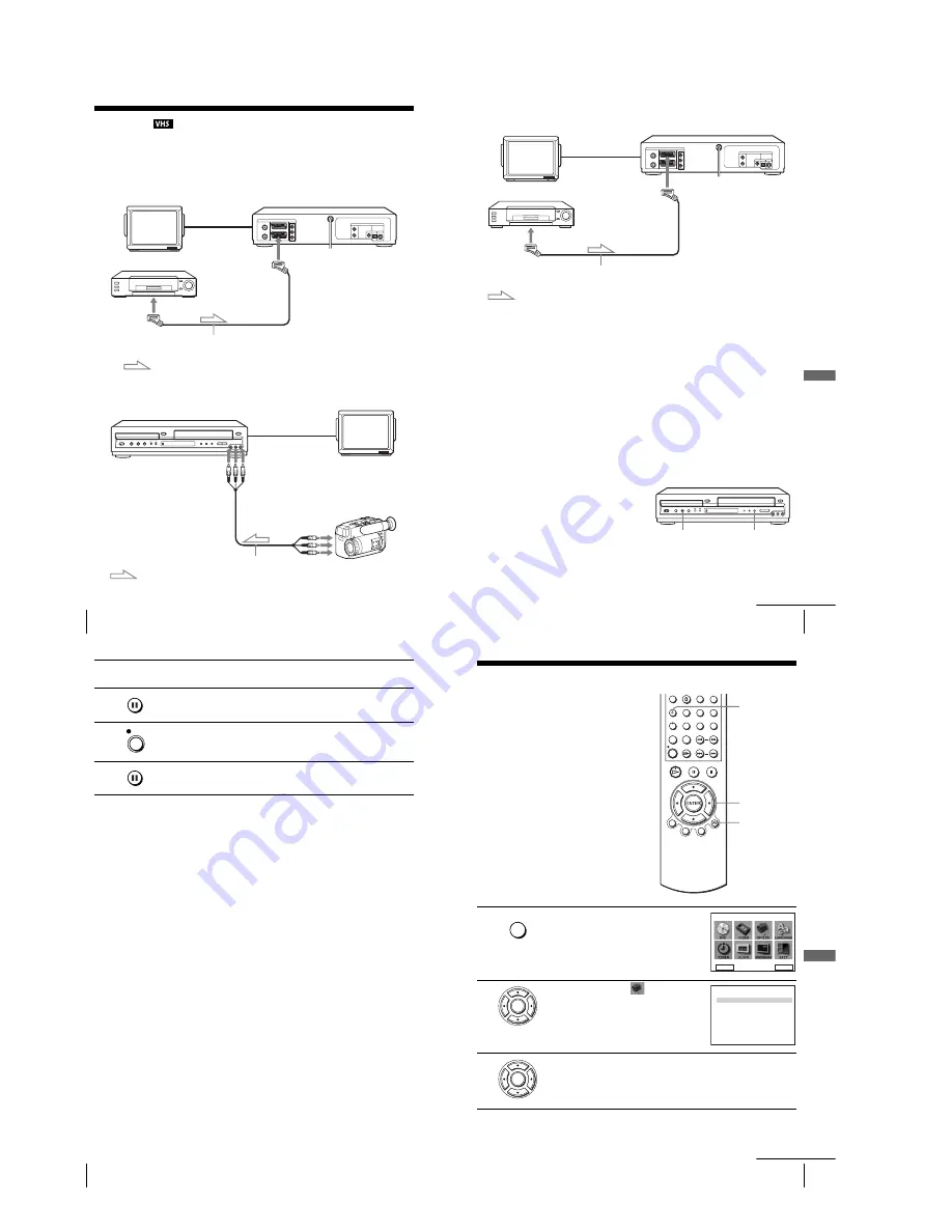
How to connect to record on this VCR
Connect the line outputs of the other VCR to the input connector of this VCR. Refer to the
examples A through C and choose the connection that best suits your VCR.
Example A
Example B
TV
LINE-1 (EURO AV)
VMC-2121HG Scart cable (not supplied)
Scart
(EURO-AV)
: Signal flow
Your VCR (Recorder)
Other VCR (Player)
TV
audio/video cord
(not supplied)
LINE OUT
Your VCR (Recorder)
Other VCR (Player)
: Signal flow
LINE-2 IN
t
/
o
L/R
93
Editing
VCR Ad
ditio
nal Ope
ration
s
Example C
How to connect to a stereo system
Connect the LINE-2 IN
t
/
o
L/R jacks on this DVD-VCR to the audio output jacks on the
stereo system, using the RK-C510HG audio cable (not supplied).
Notes
• Make sure you connect the plugs to jacks of the same colour.
• If the other VCR is a monaural type, leave the red plugs unconnected.
• If you connect this VCR to both the LINE IN and LINE OUT jacks of the other VCR, select
the input correctly to prevent a humming noise.
• If the other VCR does not have a Scart (EURO-AV) connector, use the VMC-2106HG cable
instead and connect the cable to the line out jacks of the other VCR.
• When you connect another VCR to the LINE-3 or LINE-2 connector, press INPUT SELECT
to display “LINE 3”or “LINE 2” in the display window.
Operation (when recording on this VCR)
Before you start editing
• Turn on your TV and set it to the video
channel.
• Press INPUT SELECT to display the
connected line in the display window.
• Press SP/LP to select the tape speed, SP or
LP.
• Press SELECT VIDEO to control the
VCR.
TV
LINE-3
VMC-2121HG Scart cable (not supplied)
Scart
(EURO-AV)
: Signal flow
Your VCR (Recorder)
Other VCR (Player)
z
REC
X
continued
94
Editing
To stop editing
Press the
x
buttons on both VCRs.
Tip
• To cut out unwanted scenes while editing, press
X
on this VCR when an unwanted scene
begins. When it ends, press
X
again to resume recording.
1
Insert a source tape with its safety tab removed into the other (playback)
VCR. Search for the point to start playback and set it to playback pause.
2
Insert a tape with its safety tab in place into this (recording) VCR. Search
for the point to start recording and press
X
to set it to playback pause.
3
Press REC
z
on this VCR to set it to recording pause.
4
To start editing, press the
X
buttons on both VCRs at the same time.
REC
95
General setup information
Ad
d
itiona
l In
fo
rm
ation
Additional Information
General setup information
Changing setup options
1
Press SET UP when the DVD player is in stop
mode.
2
Press
V
/
v
/
B
/
b
to select
(USER SET),
then press ENTER.
The “USER SET” menu appears.
3
Press
V
/
v
to select the option to change.
V/v/B/b
ENTER
SET UP
O
RETURN
SET UP
DVD SETUP
RETURN
SETUP MENU
Vv b
B
ENTER
ENTER
U S E R S E T
C O L O U R S Y S T E M
:
S M A R T T R I L O G I C
:
A U T O P O W E R O F F
: O F F
V I D E O P L U S E X T E N D :
N I C A M
:
O N
A U T O
O N
O F F
T I M E R M E T H O D : V A R I A B L E
RETURN
vV B
b
ENTER
continued
Содержание SLV-D900E
Страница 38: ...2 8E Fig 2 12 Circuit Board Locations 2 3 Circuit Board Locations VCR MAIN PCB DVD MAIN PCB FUNCTION TIMER PCB ...
Страница 39: ...3 Block Diagram 3 2E 3 1 SLV D900E D900G ...
Страница 40: ...4 PCB Diagrams 4 1 VCR Main 4 3 4 2 DVD Main 4 7 4 3 Function Timer 4 9 4 2 4 1 SLV D900E D900G ...
Страница 41: ...4 3 4 4 4 1 VCR Main COMPONENT SIDE ...
Страница 42: ...4 6 4 5 CONDUCTOR SIDE ...
Страница 43: ...4 7 4 8 4 2 DVD Main CONDUCTOR SIDE COMPONENT SIDE ...
Страница 44: ...4 10E 4 9 4 3 FUNCTION Timer COMPONENT SIDE CONDUCTOR SIDE ...
Страница 47: ...5 6 5 5 5 1 S M P S ...
Страница 48: ...5 8 5 7 FROM TO DVD Audio Video CN4 5 2 Power Drive ...
Страница 49: ...5 10 5 9 5 3 OSD VPS PDS ...
Страница 50: ...5 12 5 11 5 4 NICAM ...
Страница 51: ...5 14 5 13 5 5 A V ...
Страница 52: ...5 16 5 15 5 6 Hi Fi ...
Страница 53: ...5 18 5 17 5 7 Input Output ...
Страница 54: ...5 20 5 19 5 8 TM ...
Страница 55: ...5 22 5 21 5 9 SYSCON ...
Страница 56: ...5 24 5 23 5 10 DVD Main Micom AV Decoder ...
Страница 57: ...5 26 5 25 5 11 DVD Servo ...
Страница 58: ...5 28E 5 27 5 12 DVD Audio Video ...
Страница 60: ...6 2 6 1 2 TEST location for adjustment mode setting TEST SW709 BUTTON Fig 6 2 Function Timer PCB Top View ...


